Electronic device, vibration generator, vibration-type reporting method, and report control method

a technology of electronic devices and user interfaces, applied in mechanical vibration separation, navigation instruments, instruments, etc., can solve problems such as inability to fully press buttons, invalid operation, and inability to report audio in a noisy environment such as in the str

Inactive Publication Date: 2007-11-06
NTT DOCOMO INC
View PDF45 Cites 225 Cited by
  • Summary
  • Abstract
  • Description
  • Claims
  • Application Information

AI Technical Summary

Benefits of technology

[0058]According to the present invention, the brake means causes the reciprocation of the weight to immediately stop in the case that generation of excitation from the excitation generating means has stopped.

Problems solved by technology

In the case of a portable electronic device provided with a keyboard or operation buttons, however, keys or operation buttons are of a reduced size, weight, and thickness to conform with an overall reduction in size, weight, and thickness of the device; and, consequently, a user may not be able to feel that a button has been fully depressed.
However, if the fingertip or pen is not properly pointed at the touch panel, or the touch panel is not pressed with sufficient force, the operation will be invalid.
There are other types of electronic devices which report to a user, by way of a beep sound and the like, that an operation input has been received, but such an audio report is almost completely ineffective in a noisy environment such as in a street.

Method used


Image

  • Electronic device, vibration generator, vibration-type reporting method, and report control method
  • Electronic device, vibration generator, vibration-type reporting method, and report control method
  • Electronic device, vibration generator, vibration-type reporting method, and report control method

Examples


fourth embodiment

[D: Fourth Embodiment]

[0219]In this embodiment, description will made on a portable electronic device switching the location where vibration is caused to a touch panel or hand-touched portion of a housing in accordance with whether the portable electronic device is being held by a user. Note that in the present embodiment, the same reference numerals are used for portions common with the first embodiment. Further, explanations of portions common with the first embodiment will be omitted.

[0220][D-1: Configuration of Fourth Embodiment]

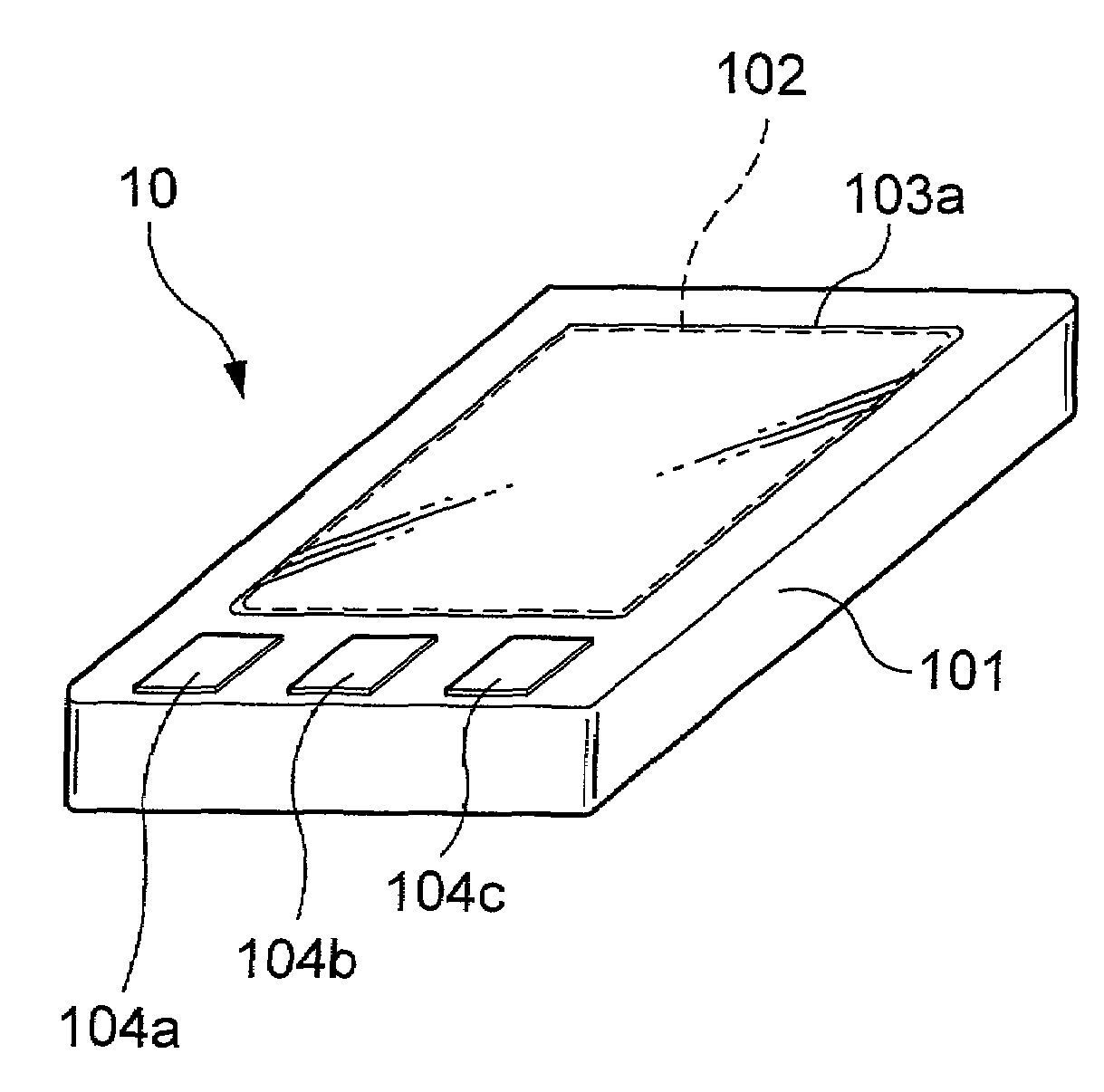
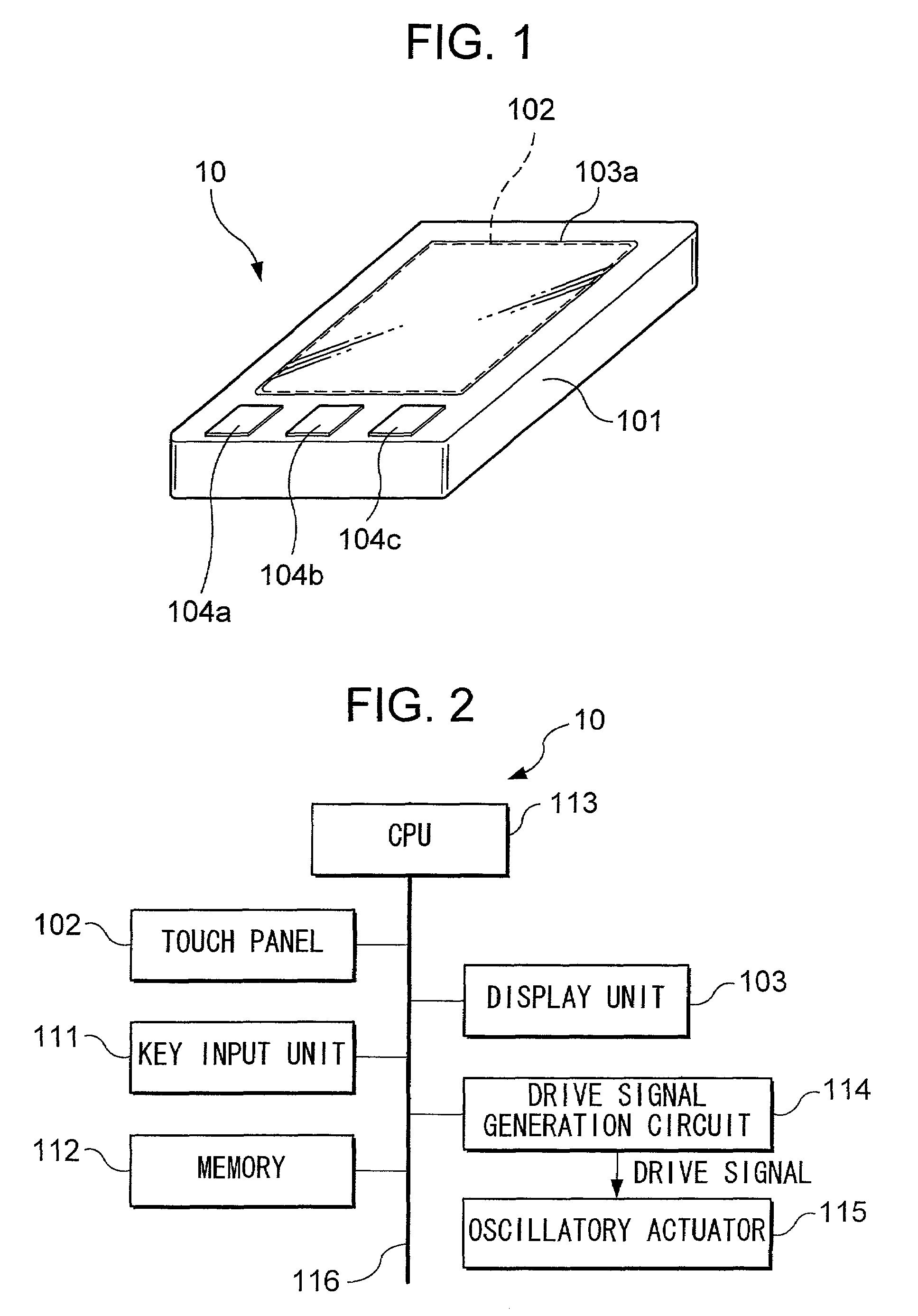
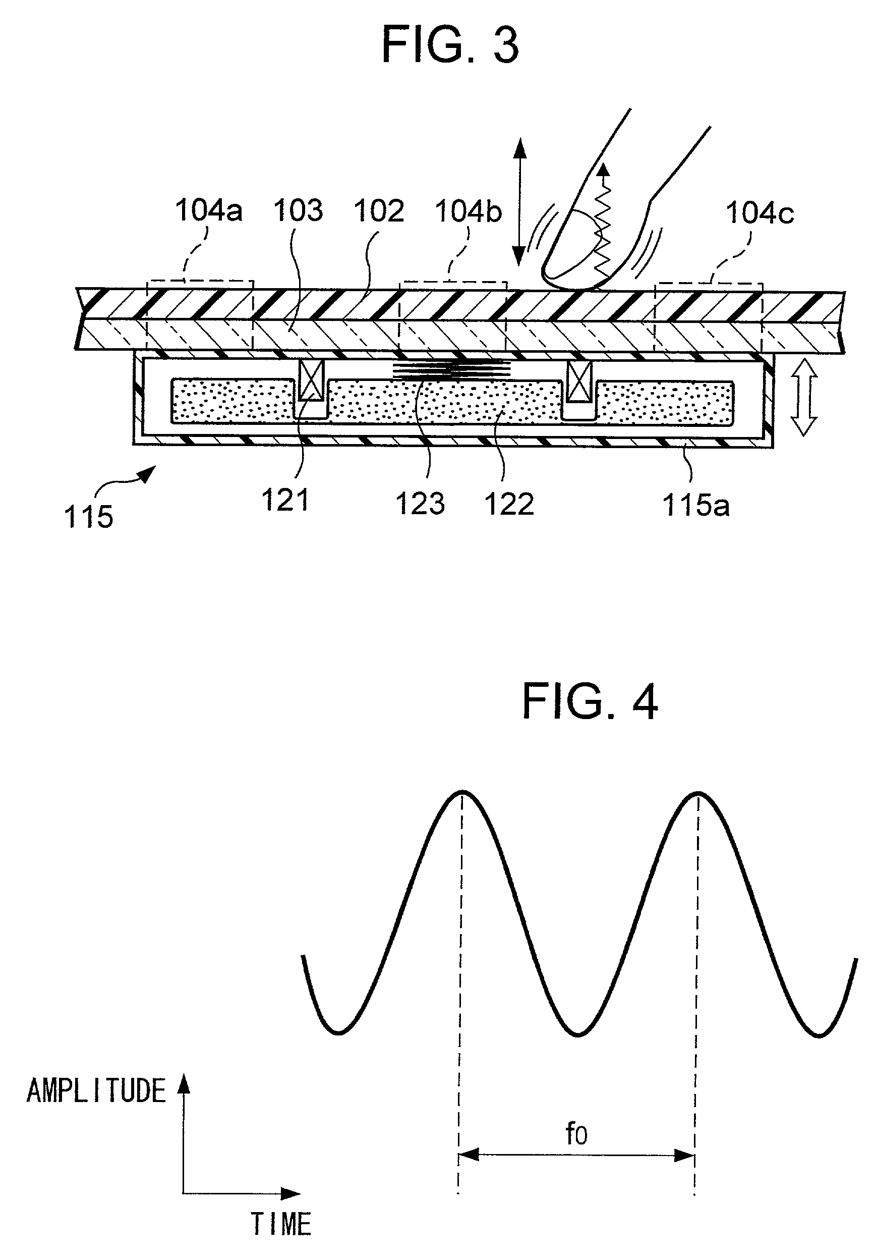
[0221]FIG. 16 is a view illustrating an internal structure of a PDA 40 according to this embodiment. In the figure, the PDA 40 has a liquid crystal display panel 103a over which a touch panel 102 is laid. The display screen of the liquid crystal display panel 103a covers the opening of the main case 401. Further, the rear surface of the liquid crystal display panel 103a is provided with an oscillatory actuator 115a. This oscillatory actuator 115a causes ...


PUM


Abstract

An electronic device drives an oscillatory actuator to cause generation of vibration when it is detected that an operation input to a touch panel or operation key has been received. The electronic device causes, by this vibration, the touch panel and operation key to vibrate in a direction perpendicular to their respective front surfaces. Alternatively, the housing of the electronic device is made to vibrate. Further, the oscillatory actuator has a weight, a support member for supporting the weight to allow it to reciprocate, and connected to the touch panel or housing or other vibratory member of the electronic device, or vibratory member of the base member of the oscillatory actuator in contact with the vibratory member, and a mechanism for imparting a magnetic force or electrostatic force to cause reciprocal movement of the weight.

Description

TECHNICAL FIELD[0001]The present invention relates to a user interface and vibration generation mechanism of an electronic device.BACKGROUND ART[0002]PDAs (personal digital assistants), personal computers, ATMs (automatic teller machines), and other various types of electronic devices have, for example, operation buttons or keyboards, touch panels, and other user interfaces. Users use these user interfaces to perform operation inputs to the electronic equipment, such as inputting words and selecting a processing to be executed.[0003]In the case of a portable electronic device provided with a keyboard or operation buttons, however, keys or operation buttons are of a reduced size, weight, and thickness to conform with an overall reduction in size, weight, and thickness of the device; and, consequently, a user may not be able to feel that a button has been fully depressed. To confirm if depression of keys or operation buttons has been received in a portable electronic device, a user mu...

Claims


Application Information

Patent Timeline
Patent Type & Authority Patents(United States)
IPC IPC(8): G09G5/00G06F3/02B06B1/04B06B1/14B06B1/16G06F1/16G06F3/00G06F3/01G06F3/041G06F3/048H02K33/18H04M1/00
CPCG01C21/3664G06F1/1626G06F1/1637G06F3/016G06F3/04886G06F1/169G06F2203/014G06F3/02
Inventor FUKUMOTO, MASAAKISUGIMURA, TOSHIAKI
Owner NTT DOCOMO INC
Why Eureka
Try Eureka