Drill powered cable cutter

a cutter and drill-powered technology, applied in the field of drill-powered cable cutters, can solve the problems of cable injuries in larger cables, slow tools, and too large cable classes to be cut using ordinary hand tools

Inactive Publication Date: 2007-11-13
IDEAL IND INC
View PDF31 Cites 48 Cited by
  • Summary
  • Abstract
  • Description
  • Claims
  • Application Information

AI Technical Summary

Benefits of technology

[0005]The drive assembly includes a simple worm and worm gear construction. The worm is mounted on the drive shaft and rotates with the shaft along a first axis. The worm gear is mounted on a worm gear shaft along a second axis which is perpendicular to the first axis. The worm gear shaft is supported by three separate bearings. It has been found that three bearings are needed to prevent failure of the worm gear shaft. The worm engages the worm gear for rotation of the worm gear and the worm gear shaft. The worm gear shaft carries a drive gear which operatively engages at least one of the cutting blades for moving one of the blades relative to the other. A segment gear formed on at least one of the cutting blades engages the drive gear.
[0006]A torque arm is slidably attached at one end to the cutter housing. A torque arm clamp releasably fixes one end of the torque arm to the housing. The other end of the torque arm has a hook which is adapted to curve around the handle of the drill. The torque arm is arranged so it will adapt to any size drill. The torque arm counteracts the torque produced on the cutter by the rotational movement. In other words, it prevents the housing from spinning relative to the power drill. The torque arm will also prevent the cutter from inadvertently falling when the cutter is disconnected from the drill.

Problems solved by technology

This class of cable is too large to be cut using ordinary hand tools.
These tools are slow and they can potentially cause injuries in larger cables due to the repeated actuations required.
Other prior art hand tools have elongated handles for extra leverage to cut larger diameter cables, but these tools are so large as to be unwieldy and inconvenient to carry around.
Other drawbacks of prior cable cutters include the weight and bulk of an electric motor and power source therefor which are built into the cutting tool.
In any case, a tool with a dedicated motor and power supply simply duplicates the equipment an electrician already has.
This adds cost, weight and bulk to the equipment needed for a particular job.

Method used


Image

  • Drill powered cable cutter
  • Drill powered cable cutter
  • Drill powered cable cutter

Examples


Embodiment Construction

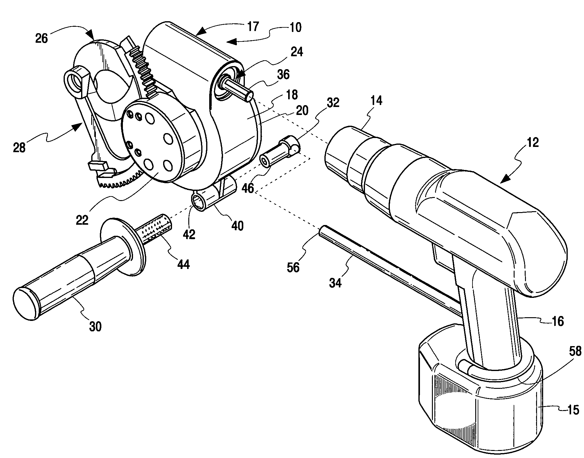
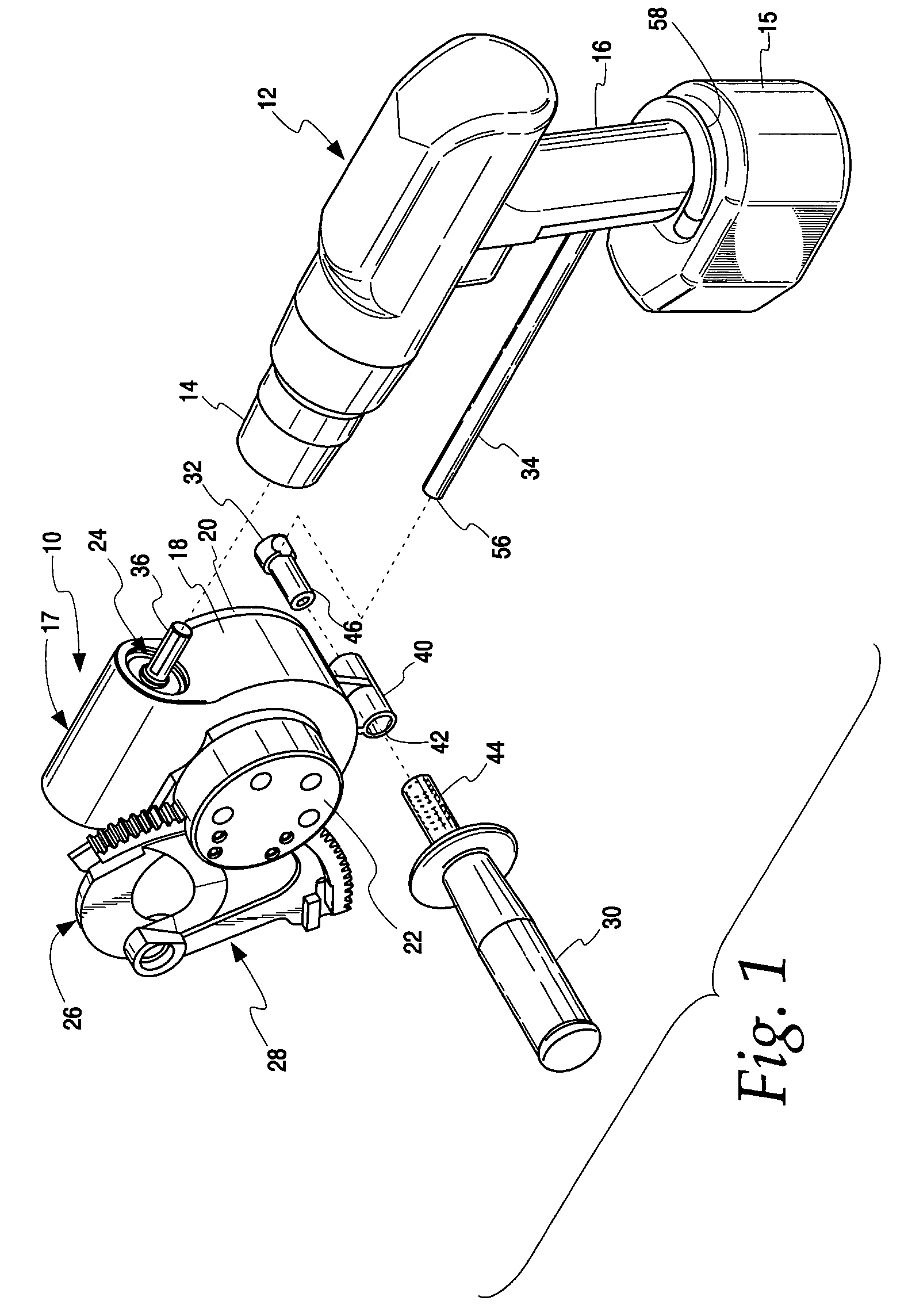
[0026]The cable cutter of the present invention is shown generally at 10 in FIG. 1. The cutter is adapted for removable engagement with a standard, hand-held power drill 12. The drill includes the usual chuck 14 and handle 16. A battery pack 15 may be attached at the bottom of the handle. For purposes of description the front of the cutter will be considered the portion facing the drill 12 in FIG. 1. Accordingly, the right side of the cutter is the side with the cover 20 while the left side of the cutter is the side with the end cap 22. This is the orientation that would most commonly be seen by a user when operating the cable cutter. Thus, references herein to the lateral direction will mean along the left-right direction while references to the longitudinal direction will mean along the front to back direction, i.e., parallel to the axis of the drive shaft 36.

[0027]Continuing with a description of the major components of the cable cutter in FIG. 1, there is a main body or enclosur...


PUM

PropertyMeasurementUnit
diameteraaaaaaaaaa
forceaaaaaaaaaa
weightaaaaaaaaaa

Abstract

A cable cutter for attachment to a power drill has a housing, first and second cutting blades connected to the housing for movement relative to one another and a drive assembly releasably engageable with the chuck of the drill and operatively engaged with at least one of the cutting blades. The drive assembly includes a worm mounted on a drive shaft, a worm gear and a drive gear mounted on a main shaft, and a segment gear formed on one of the cutting blades. The worm and worm gear which are in engagement, as are the drive gear and segment gear. The main shaft is supported in the housing by three bearings. A torque arm is attached at one end to the housing and adapted at its other end to engage the handle of the drill. A reversible stabilizing handle attaches to the housing to allow the user to securely grip the housing during cutting operations.

Description

BACKGROUND OF THE INVENTION[0001]The present invention relates to cable cutters and, in particular, to a drill-powered cable cutter which can be removably attached to a standard, hand-held power drill having a rotating chuck and handle.[0002]Cable cutters are used to cut large electrical cables of the type used in high voltage or high current applications. Such cables can vary in diameter but generally they can be an inch in diameter or larger. This class of cable is too large to be cut using ordinary hand tools. Ratchet cable cutters are known which require repeated actuations to slowly force a cutting blade through a cable. These tools are slow and they can potentially cause injuries in larger cables due to the repeated actuations required. Other prior art hand tools have elongated handles for extra leverage to cut larger diameter cables, but these tools are so large as to be unwieldy and inconvenient to carry around. This has lead to the development of power tools for cutting lar...

Claims


Application Information

Patent Timeline
Patent Type & Authority Patents(United States)
IPC IPC(8): B26B15/00B23B45/00B23D29/00B25F3/00
CPCB23D29/002Y10T83/8835Y10T83/8759Y10T83/8763B26B15/00B25F3/00B23B45/00
Inventor KONEN, BRUCE P.
Owner IDEAL IND INC
Why Eureka
Try Eureka