
Multiple-axis linear accelerometer

a linear accelerometer and multi-axis technology, applied in the field of accelerometers, can solve the problems of high cost and undesired packaging sensitivity of conventional vertical sensing accelerometers, and the large complexity of the vertical stack structure employed in the above conventional linear accelerometers, and achieve the effects of reducing the cost of vertical sensing accelerometers

Active Publication Date: 2007-11-13
GOOGLE LLC
View PDF58 Cites 70 Cited by
  • Summary
  • Abstract
  • Description
  • Claims
  • Application Information

AI Technical Summary

Benefits of technology

The present invention provides a multiple-axis accelerometer that can sense acceleration in multiple directions. It includes a support substrate and fixed and movable capacitive plates that form variable capacitors for sensing acceleration in different directions. The accelerometer can measure acceleration magnitude and direction in three orthogonal axes, also known as a tri-axis accelerometer. The technical effect of this invention is to provide a more accurate and reliable sensor for measuring acceleration in multiple directions.

Problems solved by technology

The vertical stacked structure employed in the aforementioned conventional linear accelerometer generally requires significant process complexities in the fabrication of the device using bulk and surface micro-machining techniques.
As a consequence, conventional vertical sensing accelerometers typically suffer from high cost and undesired packaging sensitivity.
Additionally, many prior known approaches employ electrode anchors fixed along the perimeter of the suspended proof mass, which results in unwanted sensitivity due to packaging induced stress.

Method used


Image

  • Multiple-axis linear accelerometer
  • Multiple-axis linear accelerometer
  • Multiple-axis linear accelerometer

Examples


Embodiment Construction

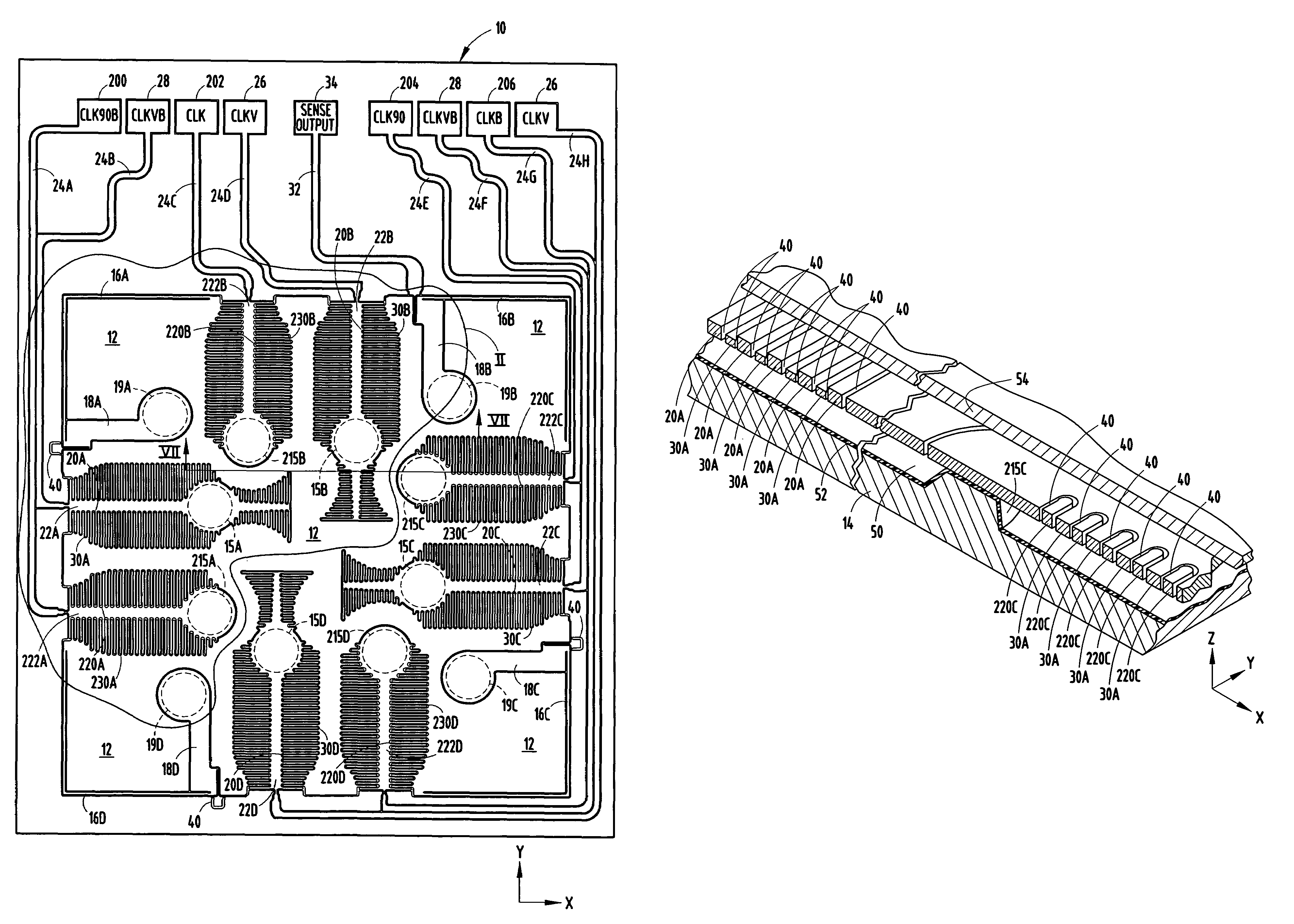
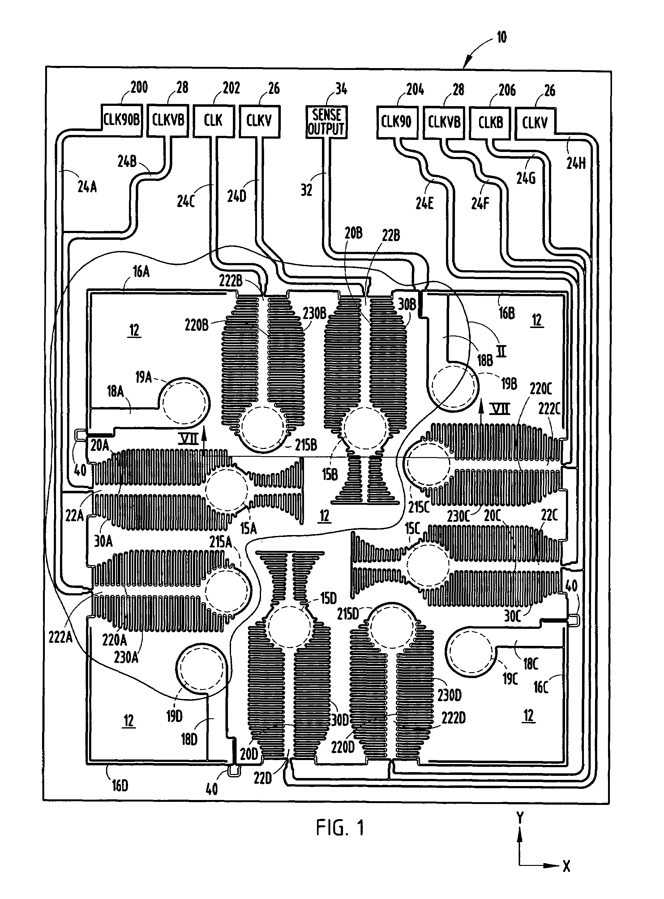
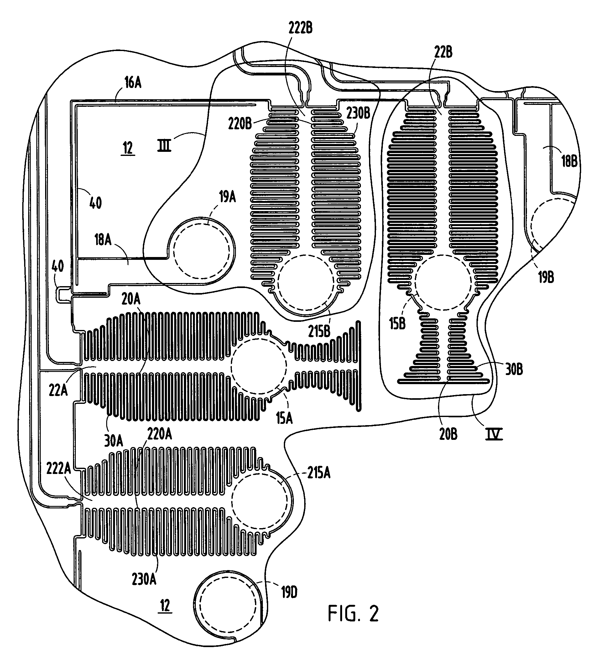
[0023]Referring to FIGS. 1-7, an accelerometer 10 is illustrated according to one embodiment of the present invention for sensing acceleration along multiple orthogonal sensing axes. The accelerometer 10 shown and described herein is a three-axis linear accelerometer for sensing linear acceleration in both upward and downward directions of the vertical Z-axis, and in both negative and positive directions in both the X-axis and the Y-axis, according to one embodiment. The Z-axis extends perpendicular to the plane defined by the X- and Y-axes. The accelerometer 10 may be employed as a two-axis accelerometer for sensing linear acceleration in either of the X- and Y-axes, or any combination of X-, Y- and Z-axes, in addition to the vertical Z-axis. Further, it should be appreciated that the accelerometer 10 could be employed to sense angular acceleration or angular velocity, such as angular acceleration or angular velocity about the Z-axis, in addition to linear acceleration along the ve...


PUM


Abstract

A three-axis accelerometer is provided for sensing acceleration in three orthogonal axes. The accelerometer includes a support substrate, fixed electrodes having fixed capacitive plates fixed to the support substrate, and a movable inertial mass having movable capacitive plates capacitively coupled to the fixed capacitive plates. The accelerometer includes banks of fixed and movable capacitive plates oriented to sense acceleration in orthogonal X- and Y-axes. Additionally, the accelerometer includes fixed and movable capacitive plates having a height variation between adjacent plates to sense acceleration in the vertical Z-axis. Input signals are applied to certain electrodes coupled to the fixed capacitive plates, and an output signal is generated on the inertial mass, which is indicative of acceleration in each of the sensing axes. The output signal may be further processed to generate individual acceleration outputs for each of the sensing axes.

Description

CROSS-REFERENCE TO RELATED APPLICATION[0001]This application is a continuation-in-part of U.S. application Ser. No. 11 / 081,427 entitled “LINEAR ACCELEROMETER,” filed on Mar. 16, 2005 now abandoned, the entire disclosure of which is hereby incorporated herein by reference.TECHNICAL FIELD[0002]The present invention generally relates to acceleration sensors (i.e. accelerometers) and, more particularly, relates to a micro-machined capacitively coupled accelerometer for sensing acceleration in multiple directions.BACKGROUND OF THE INVENTION[0003]Accelerometers are commonly employed to measure the second derivative of displacement with respect to time. In particular, linear accelerometers measure linear acceleration generally along a sensing axis. Linear accelerometers are frequently employed to generate an output signal (e.g., voltage) proportional to linear acceleration for use in any of a number of vehicle control and motion based systems. For example, the sensed output from a linear a...

Claims


Application Information

Patent Timeline
Patent Type & Authority Patents(United States)
IPC IPC(8): G01P15/125
CPCG01P15/18G01P15/125G01P2015/082
Inventor ZARABADI, SEYED R.CHRISTENSON, JOHN C.
Owner GOOGLE LLC
Learn More