Structure of a screw nailer

a screw and nailer technology, applied in the direction of screwdrivers, wrenches, power-driven tools, etc., can solve the problems of affecting the quality of the screw's locking movement, the stability and endurance of the snap's locking movement becoming gradually degenerated, etc., to increase the accuracy and secure operation of the screw nailer, and seriously affect the nailing operation.

Inactive Publication Date: 2007-11-13
BASSO IND CORP
View PDF6 Cites 7 Cited by
  • Summary
  • Abstract
  • Description
  • Claims
  • Application Information

AI Technical Summary

Benefits of technology

[0010]Constructed through above, the present invention mainly adds the blockage fixer 70, and by the position of the blockage fixer to nail the screw by its rotational inertia when the rotary driver of the screw nailer is rotating in the direction with preset angle to keep the nail belt 40 from turning the angles, so that the screws may be nailed accurately and securely to the designed location; this way, it indeed solves the problem of the conventional screw nailer, in which the nail belt is unable to secure the position and seriously affects the nailing operation; this invention has largely increase the accuracy, quality and effects of the screw nailer operation, and is practical and preferred application.

Problems solved by technology

Because when the nail belt 15 moves, the fixed position is achieved by locking the coiled wedge end 141 of the snap 14 in the fixation slot 112 of the driving wheel 11; however, after the snap 14 has been used for a while, it may become crooked and cause elastic fatigue, thus, the stability and endurance of the snap's locking movement becomes gradually degenerated and could not meet the requirement, and “over-turn” appears at the end of each turn of the driving wheel 11, which causes the driving wheel 11 to fail to position the nail belt 15 in the designated location, so that it is easy to nail the screws, which are on the nail belt, to the wrong position, and this affects the coming nailing movement, because slightly dispositioned nail can easily cause the nailing target to look crooked, and further affect its quality besides it may disrupt the process of nail positioning.

Method used


Image

  • Structure of a screw nailer
  • Structure of a screw nailer
  • Structure of a screw nailer

Examples


Embodiment Construction

[0022]The features and the advantages of the present invention will be more readily understood upon a thoughtful deliberation of the following detailed description of a preferred embodiment of the present invention with reference to the accompanying drawings.

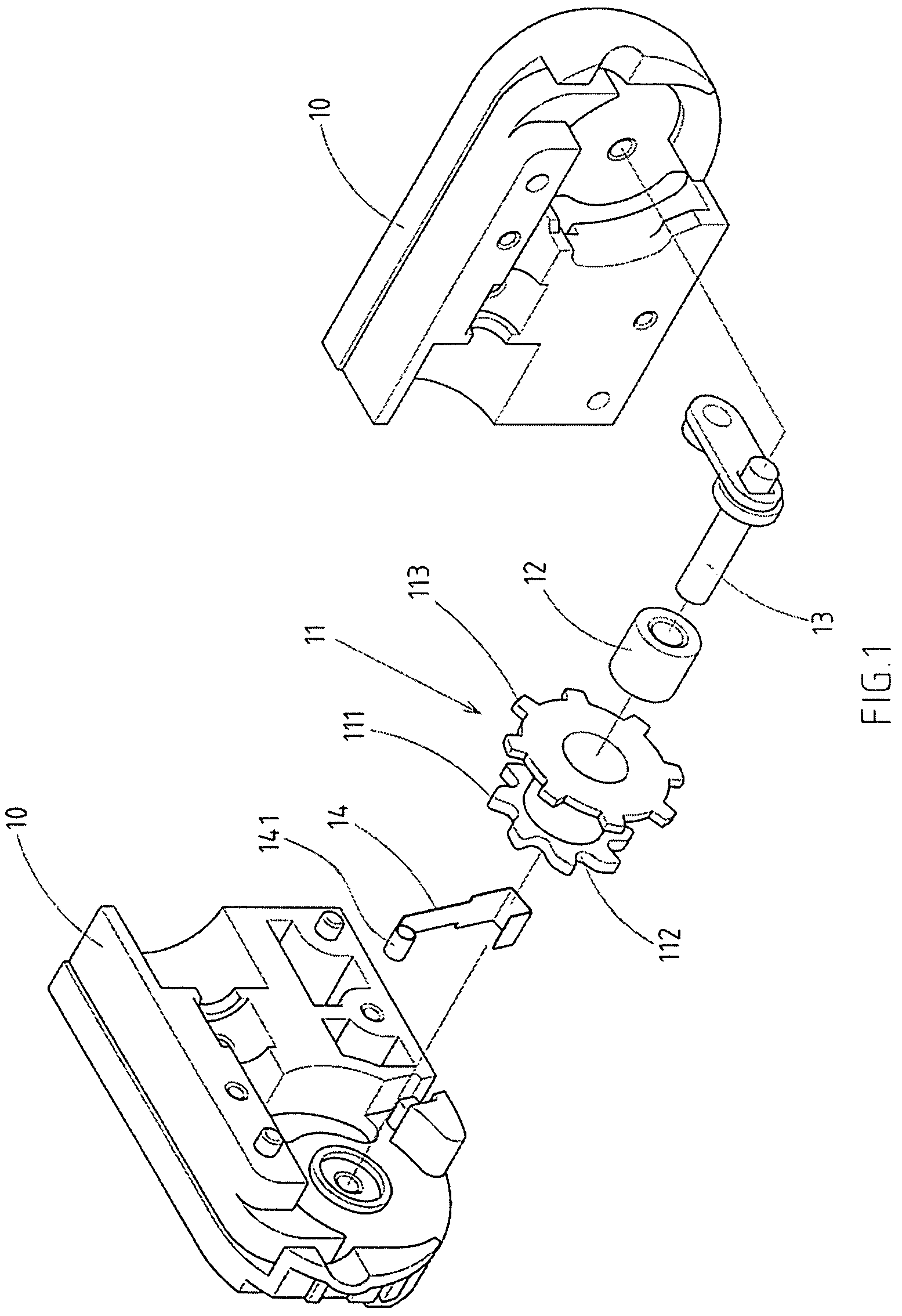
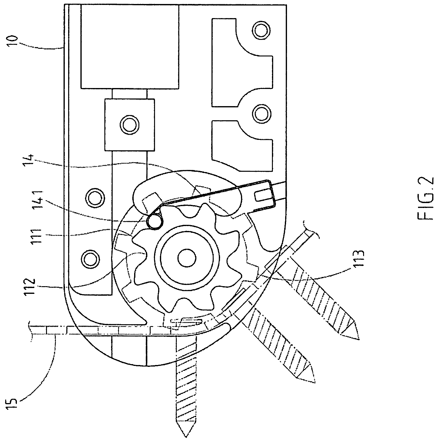
[0023]As shown in FIGS. 1-3, there is a preferred embodiment of the present invention.

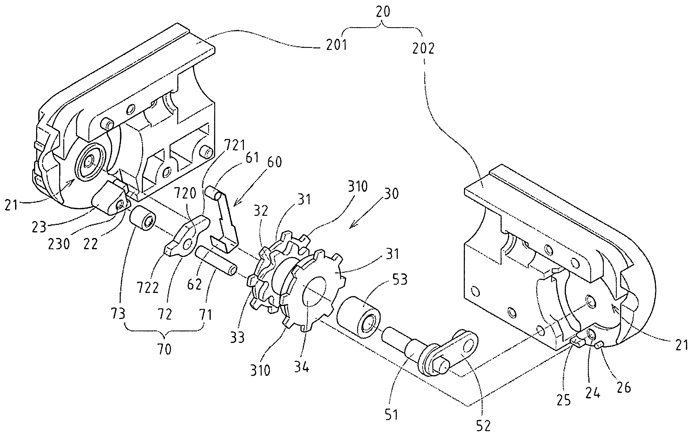
[0024]The invention includes a body 20, which consists of two block-shaped components 201202 setting correspondingly; and a functioning space 21 is formed inside after both of them are put together; among them, a fixation slot 22 and a protruding block 23 are placed inside a module 201, and a pivotal hole 230 is placed on the protruding block, and a pivotal hole 24, are protrusion 25 and a fixation column 26 are placed on the corresponding site on the other module.

[0025]There is a rotary driver 30, which is made gear like, is to be placed in the functioning space 21 of the body 20, so that it may rotate from a fixed point; the rotary driver 30 ...


PUM


Abstract

The structure of a screw nailer includes a body with a functional space inside; a rotary driver, placed in the functioning space rotated from a point of support and having a gear wheel that moves the nail belt; a one-way driving component moving the rotary driver in a single direction; an indexing fixer creating elastic positioning when the rotary driver turns in a direction in a preset angle, so that the rotary driver achieves the indexing positioning. A blockage fixer, and by position of the blockage fixer to nail the screw by rotational inertia when the rotary driver of the screw nailer is rotating in direction with preset angle to keep the nail belt from turning the angles, so that the screws may be nailed accurately and securely to the designated location, and largely increase the accuracy, quality and effects of the screw nailer operation.

Description

RELATED U.S. APPLICATIONS[0001]The present application is a continuation-in-part of U.S. patent application Ser. No. 11 / 001,394, filed on Dec. 1, 2004, and entitled “SCREW-FEEDING DEVICE FOR A SCREW-DRIVING TOOL”, now U.S. Pat. No. 7,121,174, issued on Oct. 17, 2006.STATEMENT REGARDING FEDERALLY SPONSORED RESEARCH OR DEVELOPMENT[0002]Not applicable.REFERENCE TO MICROFICHE APPENDIX[0003]Not applicable.FIELD OF THE INVENTION[0004]The present invention relates generally to a screw nailer, and more particularly to a new device, which can nail the screw accurately to the designated location by adding a blockage fixer, so that when the rotary driver of the screw nailer is rotating in one angle, the screw can be nailed by its rotational inertia to prevent the nail belt from skipping.BACKGROUND OF THE INVENTION[0005]The screw nailer is an assisting device that can be installed on the end of pneumatic or electrical tool, and it is designed to move the screws along the process, so that operat...

Claims


Application Information

Patent Timeline
Patent Type & Authority Patents(United States)
IPC IPC(8): B25B23/04B25B23/06B25B21/00
CPCB25B23/045
Inventor CHANG, SHIN-NAN
Owner BASSO IND CORP
Why Eureka
Try Eureka