
Pneumatic nail gun

a nail gun and pneumatic technology, applied in the field of pneumatic nail guns, can solve the problems of high manufacturing cost of nail guns, complicated air flow passage distribution, and large gun body capacity, and achieve the effects of reducing manufacturing cost, simplifying valve control mechanism, and improving air flow passage distribution

Inactive Publication Date: 2007-11-13
DE POAN PNEUMATIC
View PDF15 Cites 49 Cited by
  • Summary
  • Abstract
  • Description
  • Claims
  • Application Information

AI Technical Summary

Benefits of technology

[0006]A pneumatic nail gun of the present invention improves the air flow passage distribution for the compressed high pressure air driving the piston upwardly move to reposit and simplifies the valve controlling mechanism required by the distribution; therefore, the manufacturing cost can be reduced.
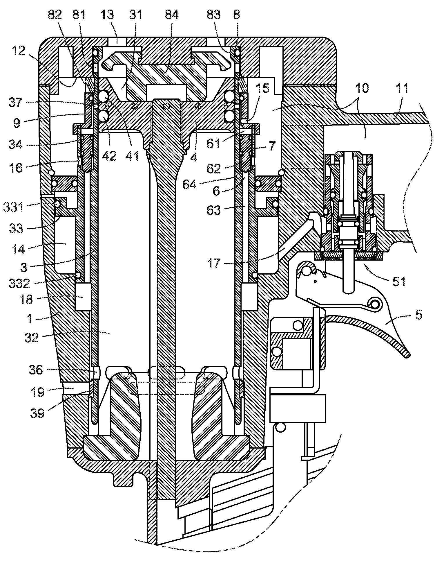
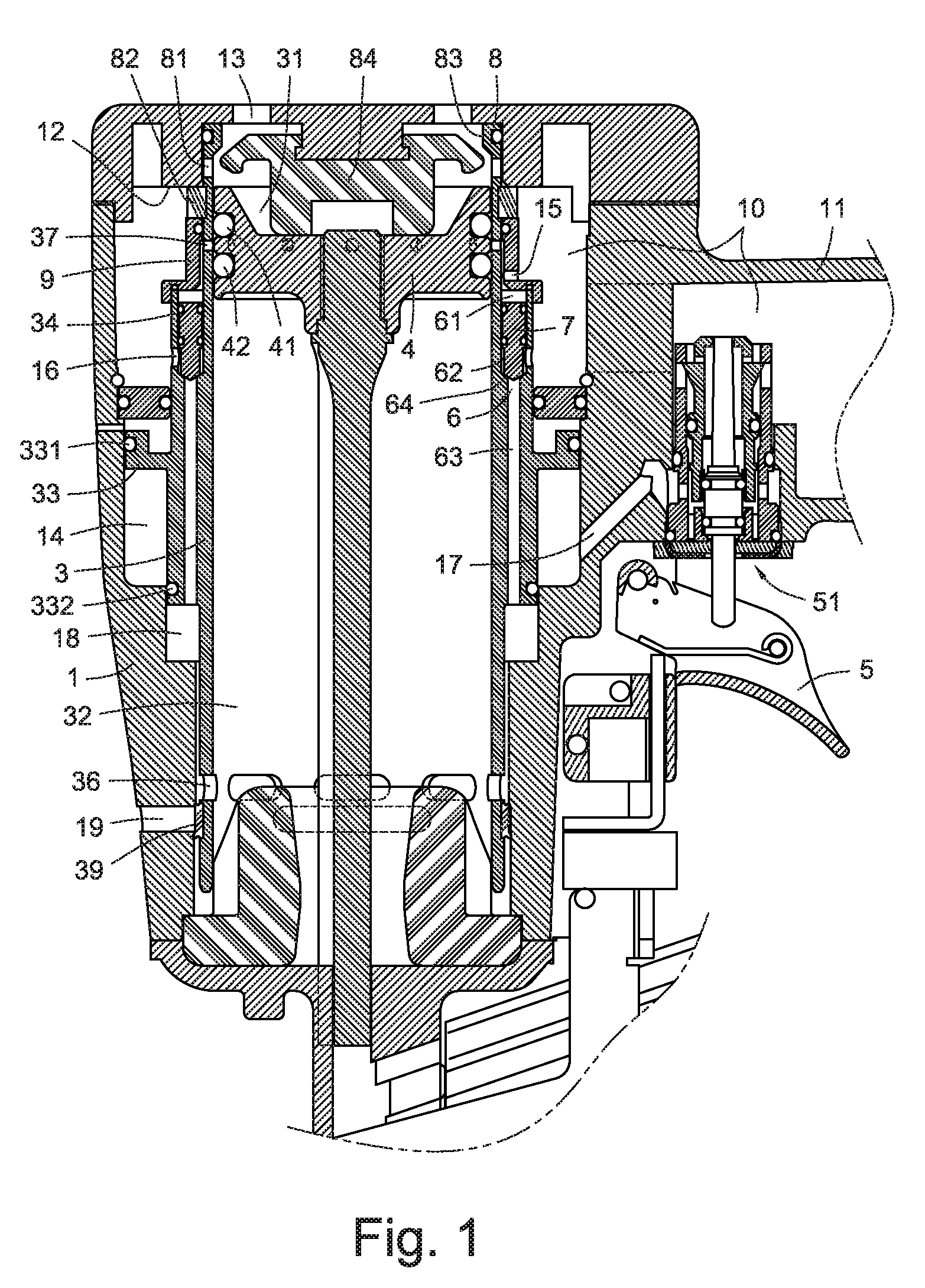
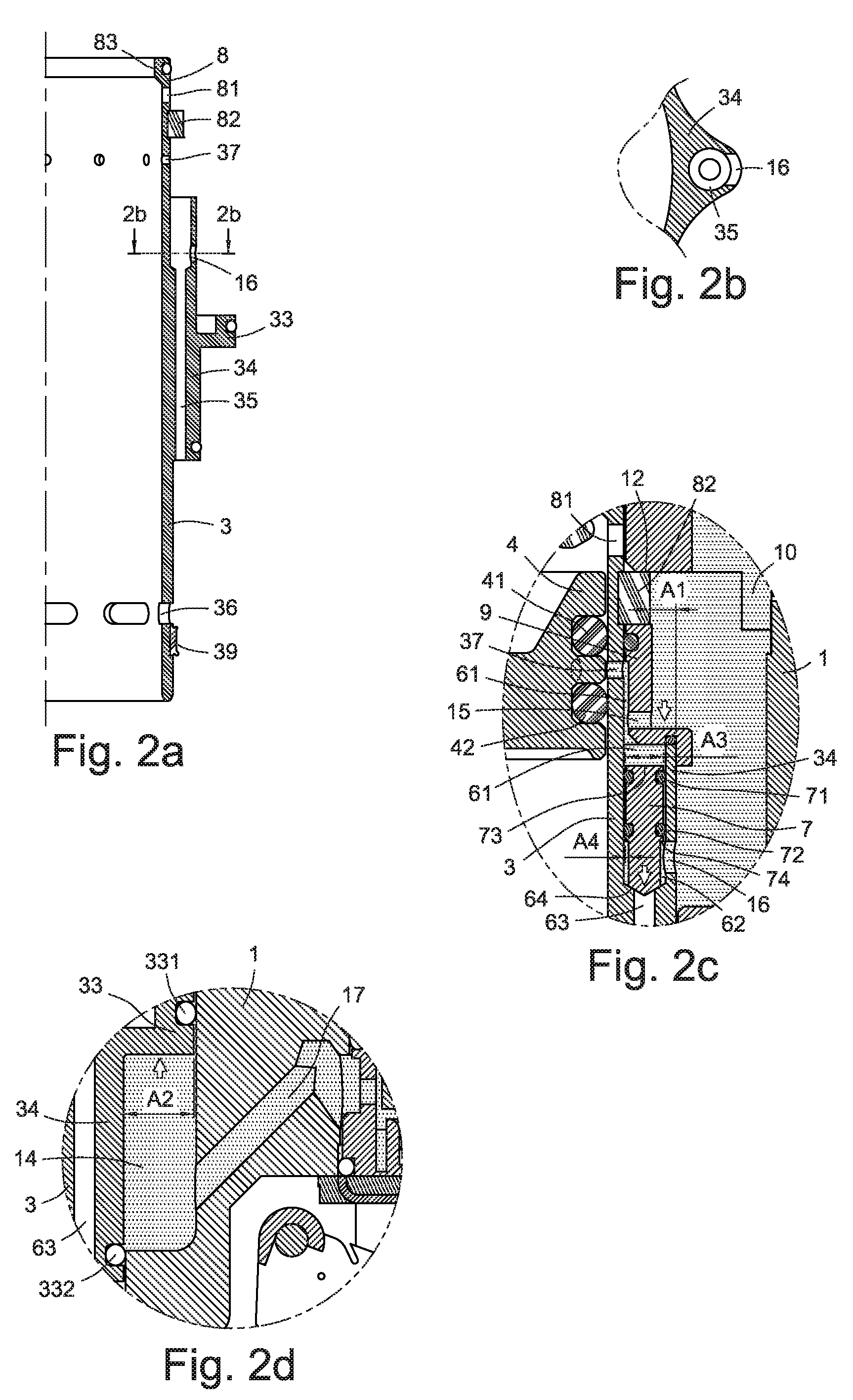
[0008]A head valve is disposed on the top of the cylinder. A valve ring is disposed on the outer wall of the cylinder so that a middle chamber is formed between the valve ring and the inner wall of the gun body to accumulate high pressure air therein. Before the trigger is pressed, the high pressure air push the cylinder moving upwardly to make the head valve close air communication between the main air housing and the top cylinder chamber. When the trigger is pressed, the middle chamber discharges air and the cylinder moves downwardly driven by the high pressure air in the main air housing to make the head valve open the air communication between the main air housing and the top cylinder chamber so as to guide the high pressure air driving the piston downwardly move to hit nails. As such, the complexities of chamber and passage design for the high pressure air in the gun body to drive the cylinder downwardly move to open valves and upwardly to close valves can be simplified.
[0009]A return passage is formed on the outer wall of the cylinder to drive the piston upwardly move for reposition, which is connected between the main air housing and the bottom cylinder chamber. As such, the return passage can provides the shorter distance connected between the main air housing and the bottom cylinder chamber to simplify the air passage.

Problems solved by technology

As such, the nail gun has a high manufacturing cost and complicated air flow passage distribution.
However, the valve control device has complicate assembly and more passages in the nail gun are needed, as well as the valve control device is installed farther away from the cylinder in the gun body so that larger capacity of gun body and higher cost are inevitable.

Method used


Image

  • Pneumatic nail gun
  • Pneumatic nail gun
  • Pneumatic nail gun

Examples


Embodiment Construction

[0020]Referring to FIG. 1, a pneumatic nail gun according to a first embodiment of the present invention is shown. The pneumatic nail gun has a gun body 1, a movable cylinder 3 installed in the gun body 1, a hitting piston 4 disposed in the movable cylinder 3, a main air housing 10 formed in the nail gun. The hitting piston 4 includes at least two air tight rings 41 and 42, which can divide the cylinder 3 into a top cylinder chamber 31 and a bottom cylinder chamber 32 when the hitting piston 4 move downward to hit nails or move upward to reposit. The main air housing 10 is disposed between a handle 11 of the nail gun and the peripheral portion of the cylinder 3 for continuously gathering high pressure air from air supply via a free end of the handle 11 to maintain a constant air pressure therein (see dots area in FIG. 3). A trigger valve 51 is disposed at one end of the main air housing 10 to be driven by a trigger 5 disposed on the gun body 1 for opening and closing air communicati...


PUM

PropertyMeasurementUnit
pressureaaaaaaaaaa
areaaaaaaaaaaa
distanceaaaaaaaaaa

Abstract

A pneumatic nail gun includes a gun body with a trigger, collecting a compressed high pressure air with a constant pressure, a movable cylinder installed in the gun body, a hitting piston disposed in the cylinder, a valve ring formed outside the cylinder, a head valve disposed on the top of the cylinder, at least one return passage formed outside the cylinder, and a valve bolt disposed in the return passage. Before the trigger is pressed, the high pressure air drives the valve ring to keep the cylinder at the upper position to close the head valve. When the trigger is pressed, the high pressure air drives the cylinder move downwardly to open the head valve for guiding the high pressure air to drive the piston downwardly move to hit nails. When the trigger is released, the high pressure air drives the valve bolt open for guiding the high pressure air via the return passage to drive the piston rapidly move upwardly to reposit.

Description

BACKGROUND[0001]The present invention relates to pneumatic nail guns, and particularly to a pneumatic nail gun having a movable cylinder for a hitting piston of the nail gun driven by the high pressure air to upwardly move for reposition and a head valve disposed on top of the movable cylinder.[0002]A typical pneumatic nail gun has a gun body, a main air housing formed in the gun body to continuously collect the compressed high pressure air for nail hitting, a movable or fixed cylinder disposed in the gun body, and a hitting piston installed inside the cylinder and divided the cylinder into a top and a bottom cylinder chambers. Moreover, a trigger disposed on the gun body may be pressed to have the high pressure air guided into the top cylinder chamber to drive the piston downwardly move for hitting the nails, and be released to have the high pressure air discharged from the top cylinder chamber and guided into the bottom cylinder chamber to upwardly move the piston for reposition.[...

Claims


Application Information

Patent Timeline
Patent Type & Authority Patents(United States)
IPC IPC(8): B25C1/04
CPCB25C1/045
Inventor WEN, WAN-FU
Owner DE POAN PNEUMATIC
Learn More