Modular lighting system and method of installation

a module and lighting technology, applied in the field of modules, can solve the problems of inability to accommodate complex curvilinear shapes, inability to maximize the efficiency of overlapping systems, uneven light distribution of coves, etc., and achieve the effect of convenient installation and easy installation

Inactive Publication Date: 2007-11-13
CATHODE LIGHTING SYST
View PDF16 Cites 40 Cited by
  • Summary
  • Abstract
  • Description
  • Claims
  • Application Information

AI Technical Summary

Benefits of technology

[0018]The present invention overcomes the problems of the prior art by providing a modular and flexible tubular lighting fixture system. The system combines pre-fabricated fixture elements connected by flexible elements to form a fluorescent light fixture which can be custom fit for easy installation. The system may advantageously include a plurality of lamps having any of a variety of lamp shapes, curves, colors, and / or sizes, which can be custom made to accommodate a particular location. The lighting system may be extremely easy to install when compared with other similar products.

Problems solved by technology

Systems which utilize a staggered lamp configuration suffer from overly bright areas of illumination where the lamps overlap, and can produce a pattern of alternating brightness when the fixtures are used in an indirect application.
Additionally, because the lamps are configured side-by-side, and not in a true linear array, even the untrained eye can see that the surfaces closest to each lamp are more brightly illuminated than those even slightly farther away.
That is, where tubular lamps are staggered side by side, the cove will exhibit uneven light distribution.
The disadvantages of the above-referenced system are that the non-overlapping lamp configuration exhibits dark spots and shadowing between the lamps, and the overlapping system is not as maximally efficient due to the relatively high lamp quantities and corresponding high wattage densities required by the overlapping feature.
Smaller radii and complex curvilinear shapes cannot be accommodated.
This is an inherent disadvantage of the system.
It is not offered as a curved or bent fixture that could accommodate curved or bent lamps needed for more complex and curved architectural requirements.
A disadvantage of the system is that it is costly to install, and must be field-assembled from a variety of components (some provided by the lighting manufacturer, and some provided by the installing contractor).
On the other hand, because the lampholders retain the ends of adjacent lamps, there is little room for adjustment of the system if adjustment is required.
The disadvantages of this product include the following:
A uniquely shaped or dimensioned custom channel must be factory-built for each unique lamp shape, requiring substantial labor, and if the fixture is dimensionally incorrect, it cannot be field-adjusted, it must be remade, along with the lamp.
There are some limitations as to how small a radius or acute angle this type of (or any type of metallic channel-based) fixture can be manufactured to duplicate.
These limitations are based on the physical properties of the material, the overall size of the channel and the limitations of the manufacturing techniques.

Method used


Image

  • Modular lighting system and method of installation
  • Modular lighting system and method of installation
  • Modular lighting system and method of installation

Examples


Embodiment Construction

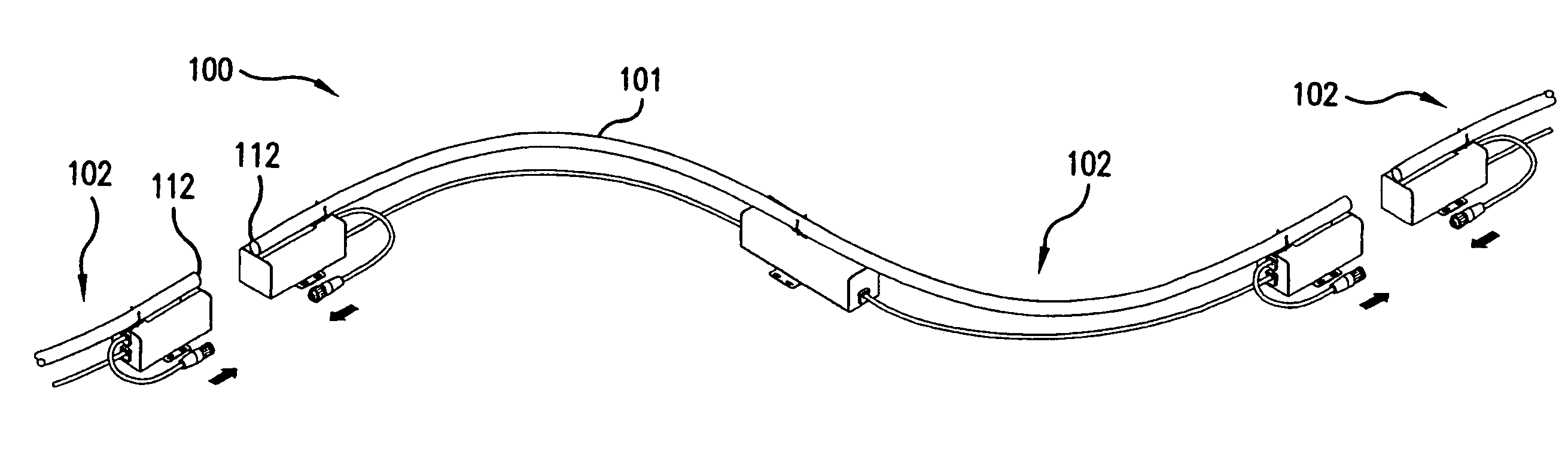
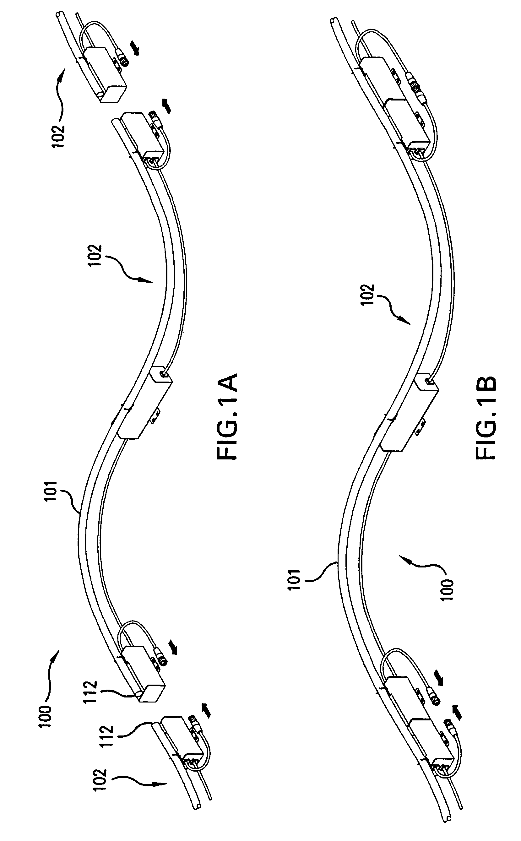
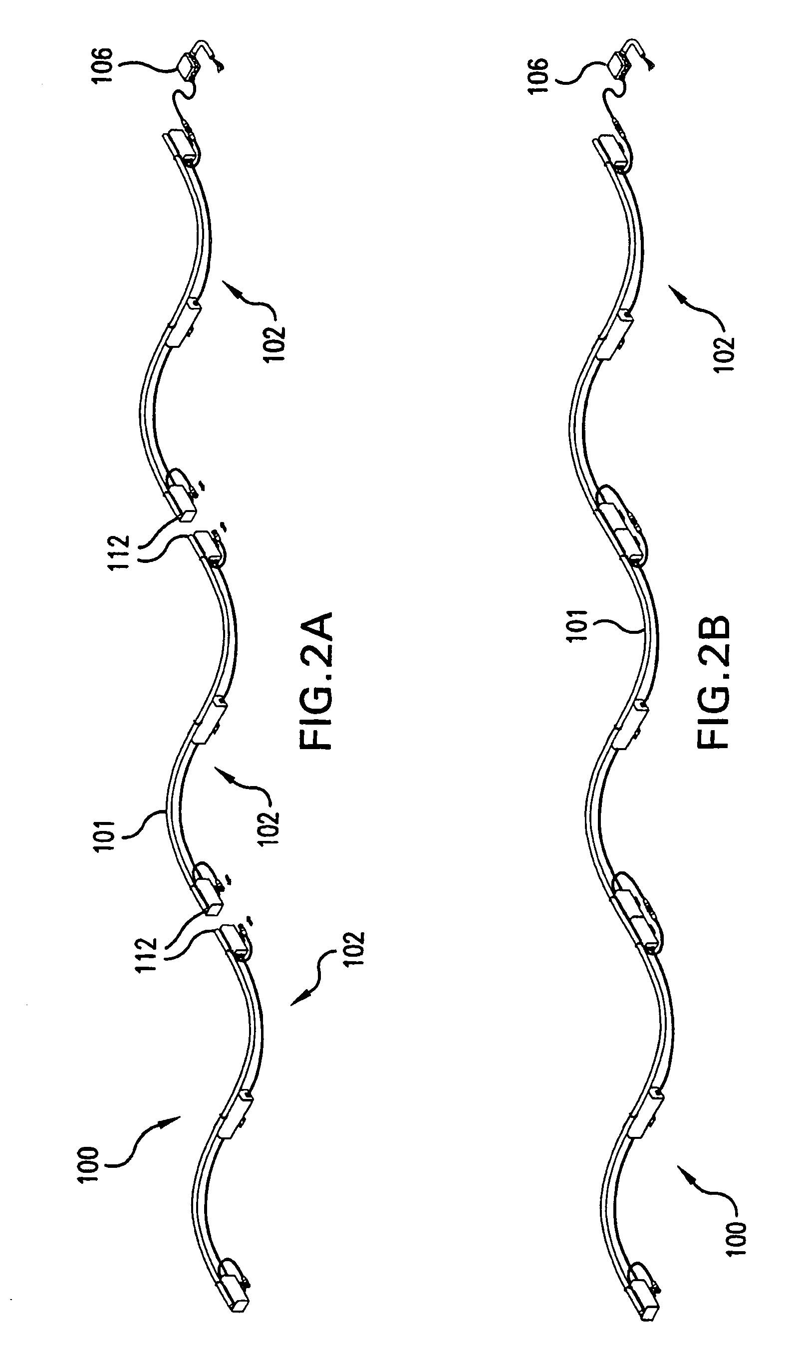
[0046]Referring now to the drawings, wherein like reference numerals indicate like elements, there is shown in FIGS. 1A-1B and 2A-2B a lighting system 100, or portions thereof, in accordance with a first exemplary embodiment of the present invention. The lighting system 100 includes a plurality of light fixtures, (composed of flexible special power cable segments which connect individual enclosures) 102 holding in-place sections of a tubular lamp (e.g. cold cathode fluorescent lamp) 101. The system 100 is intended for (but not limited to) use in indirect lighting environments, such as within a cove (not shown in FIGS. 1 or 2) to illuminate a ceiling.

[0047]FIG. 1A depicts one fixture 102 with portions of the adjacent fixtures 102, shown just prior to electrical connection and mounting of the fixtures 102. FIG. 1B shows the fixtures 102 of FIG. 1B as they would be mounted. The arrows at the left hand side of this Figure depict the electrical connection that is made, as shown by the fi...


PUM

PropertyMeasurementUnit
voltagesaaaaaaaaaa
voltagesaaaaaaaaaa
voltageaaaaaaaaaa

Abstract

A modular lighting system is formed of tubular fluorescent lamps mounted within adjustable fixtures. The fixtures are composed of rigid and flexible elements and can conform to the shape of almost any size or shape of lamp. The lamps may be of any variety of pre-determined shape, curvature or length, to meet the desired lighting requirement. Each fixture may include a lampholder, lamp retention device, mounting surface, ballast, enclosures, and specially-molded flexible special power cable which flexibly connects the rigid elements or assemblies of each fixture. Electrical connections are made between each adjacent fixture with integral male and female flexible power cords. Thus, a custom-made fluorescent lighting system is created using standardized flexibly adjustable fixtures and any variety of lamp shapes or lengths. The system may be installed and electrically connected without any disassembly or tradition field-assembled and installed wiring, minimizing effort for installation or removal.

Description

FIELD OF THE INVENTION[0001]The present invention relates to a modular, field-adjustable, linear lighting system in which one fixture universally accepts almost any size or shape of prefabricated tubular lamp.BACKGROUND OF THE INVENTION[0002]Traditionally, tubular fluorescent lighting products which are utilized to provide a continuous uninterrupted line of light for both curved and straight lighting applications can be separated into three categories:[0003]1). Fixtures and systems which use standardized straight tubular lamps in novel ways (either by overlapping, staggering or angling) to both navigate curved and straight architectural details, and overcome the problems created by the non-illuminated lamp end(s).[0004]2). Fixtures and systems which utilize straight tubular lamps (e.g., butt-ended cold cathode fluorescent lamps) which, through their unique construction, do not exhibit the typical non-illuminated lamp end(s), thus providing continuous even illumination from one end o...

Claims


Application Information

Patent Timeline
Patent Type & Authority Patents(United States)
IPC IPC(8): F21S4/00
CPCF21S2/00F21S4/003F21V23/06F21V7/005F21V19/0075F21V23/002F21V23/02F21V17/007H01R25/145F21Y2103/02F21V21/02H01B7/04F21S4/20F21Y2103/30F21V21/005
Inventor GROSSMAN, STEVEN H.GROSSMAN, RICHARD E.
Owner CATHODE LIGHTING SYST
Why Eureka
Try Eureka