Automatic gain control apparatus

a gain control and automatic technology, applied in the direction of amplifiers, code conversion, amplifiers, etc., can solve the problems of expensive off-chip capacitors, inability of analog signal 1 to adjust a dc offset,

Active Publication Date: 2007-11-13
MEDIATEK INC
View PDF34 Cites 30 Cited by
  • Summary
  • Abstract
  • Description
  • Claims
  • Application Information

AI Technical Summary

Benefits of technology

[0012]The amplitude level detector may comprise a DC level detector for detecting a DC level of the digital signal. The automatic gain control apparatus further comprises a filter, connected between the variable gain amplifier and the A / D converter, for removing a DC offset of the amplified analog signal in response to the DC level. The DC level compensates for the DC offset without an expensive external capacitor.
[0013]The present invention has the advantage of fully utilizing an input range of an A / D converter of the automatic gain control apparatus, especially has the advantage of fully utilizing an input range of the A / D converter by removing a DC offset and detecting if both the first amplitude level and the second amplitude level fall within a predetermined range.

Problems solved by technology

One disadvantage of the automatic gain control circuit 1 is that this apparatus 1 cannot adjust a DC offset of an analog signal 10.
One disadvantage of the automatic gain control apparatus 2 is that though it removes the DC offset by the DC offset detector 25, the DC offset detector 25 operates after the A / D converter 23.
Though the DC offset still can be removed by placing a high pass filter in front of the A / D converter, a required off-chip capacitor to achieve a low cut-off frequency value is costly.

Method used


Image

  • Automatic gain control apparatus
  • Automatic gain control apparatus
  • Automatic gain control apparatus

Examples


first embodiment

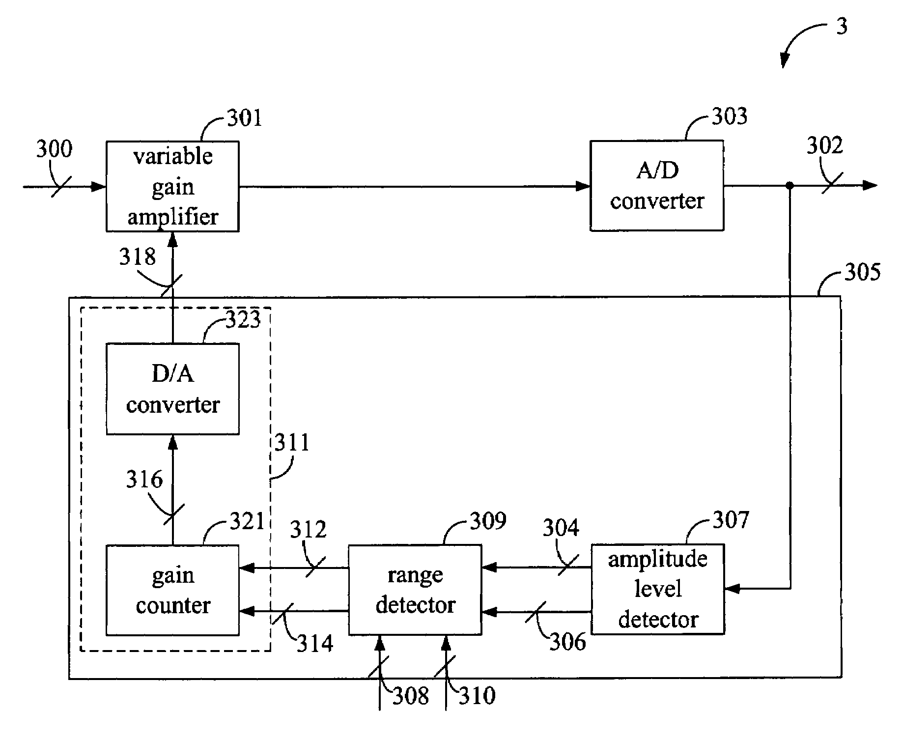
[0024]the present invention is an automatic gain control apparatus as illustrated in FIG. 3. The automatic gain control apparatus 3 comprises a variable gain amplifier 301, an A / D converter 303, and a feedback circuit 305. The variable gain amplifier 301 is configured to amplify an analog signal 300 with a gain. The A / D converter 303 is configured to convert the analog signal 300 after being amplified to a digital signal 302. The feedback circuit 305 is configured to adjust the gain in response to the digital signal 302. In other words, the feedback circuit 305 is a gain adjustment device.

[0025]The feedback circuit 305 comprises an amplitude level detector 307, a range detector 309, and a gain controller 311. The amplitude level detector 307 is configured to generate a first amplitude level 304 and a second amplitude level 306 in response to the digital signal 302. More particularly, the first amplitude level 304 responds to a top peak of the analog signal 300 and the second amplitu...

second embodiment

[0039]Accordingly, the second embodiment fully utilizes the input range of the A / D converter 303 not only by considering the first amplitude level 304 and the second amplitude level 306, but also by removing the DC offset.

third embodiment

[0040]the present invention is an automatic gain control apparatus 9 as illustrated in FIG. 9. In contrast with the second embodiment, the feedback circuit 305 further comprises a short pulse detector 901. The short pulse detector 901 is configured to determine whether the digital signal 302 is a short pulse signal, i.e., a short T signal. If yes, the short pulse detector 901 bypasses the digital signal 302. If not, the short pulse detector 901 stops the transmission of the digital signal 302. The short pulse digital signal 302 is transmitted to the amplitude level detector 307, and the amplitude level detector 307 generates the first amplitude level 304 and the second amplitude level 306 in response to the short pulse digital signal 302, i.e., the digital signal 302 after being bypassed.

[0041]Generally speaking, the peak of a short pulse signal is smaller than the peak of a long pulse signal. If the first amplitude level 304 and the second amplitude level 306 are determined based o...


PUM


Abstract

An automatic gain control apparatus receiving an analog signal and outputting a digital signal includes a variable gain amplifier, an A / D converter, and a feedback circuit. The variable gain amplifier amplifies the analog signal with a gain. The A / D converter converts the amplified analog signal to the digital signal. The feedback circuit includes an amplitude level detector, a range detector, and a gain controller. The amplitude level detector generates a first amplitude level and a second amplitude level in response to the digital signal. The range detector generates an adjustment signal in response to the first amplitude level and the second amplitude level. The gain controller adjusts a gain control level for the variable gain amplifier in response to the adjustment signal.

Description

BACKGROUND OF THE INVENTION[0001]1. Field of the Invention[0002]The present invention relates to an automatic gain control apparatus; more particularly, relates to an automatic gain control apparatus, which fully utilizes the input range of an A / D converter thereof.[0003]2. Descriptions of the Related Art[0004]An analog to digital (A / D) converter is frequently used in many kinds of electronic circuits. The function of an A / D converter is to receive an analog signal and to generate a digital signal in response to the analog signal.[0005]In some kinds of electronic circuits, it is desirable to maintain a peak value of the analog signal smaller than a maximum value accepted by the A / D converter to avoid distortion. In some further kinds of electronic circuits, the peak value is deliberately arranged close to, but still smaller than, the maximum value so that the full input range of the A / D converter may be used. The A / D converter in an automatic gain control circuit is expected to meet...

Claims


Application Information

Patent Timeline
Patent Type & Authority Patents(United States)
IPC IPC(8): H03G3/30
CPCH03M1/185H03G3/001
Inventor HSIEH, BING-YULIN, MENG-HSUEHTU, WEI-HSUAN
Owner MEDIATEK INC
Why Eureka
Try Eureka