Autofocus apparatus having a flash synchronized to an autofocus sampling time

a technology of autofocus and flash, which is applied in the field of autofocus apparatus, can solve the problems of not being able to focus on the focal lens position, and achieve the effects of low brightness, high speed and high precision focusing operation, and low reflection factor

Inactive Publication Date: 2007-11-13
RICOH KK
View PDF12 Cites 4 Cited by
  • Summary
  • Abstract
  • Description
  • Claims
  • Application Information

AI Technical Summary

Benefits of technology

[0008]In light of the problems described above, it is an object of the present invention to provide an autofocus apparatus enabli...

Problems solved by technology

This fact disadvantageously causes a focus position of t...

Method used


Image

  • Autofocus apparatus having a flash synchronized to an autofocus sampling time
  • Autofocus apparatus having a flash synchronized to an autofocus sampling time
  • Autofocus apparatus having a flash synchronized to an autofocus sampling time

Examples


Embodiment Construction

[0024]Detailed description is made hereinafter for the preferred embodiments of an autofocus apparatus according to the present invention with reference to the attached drawings.

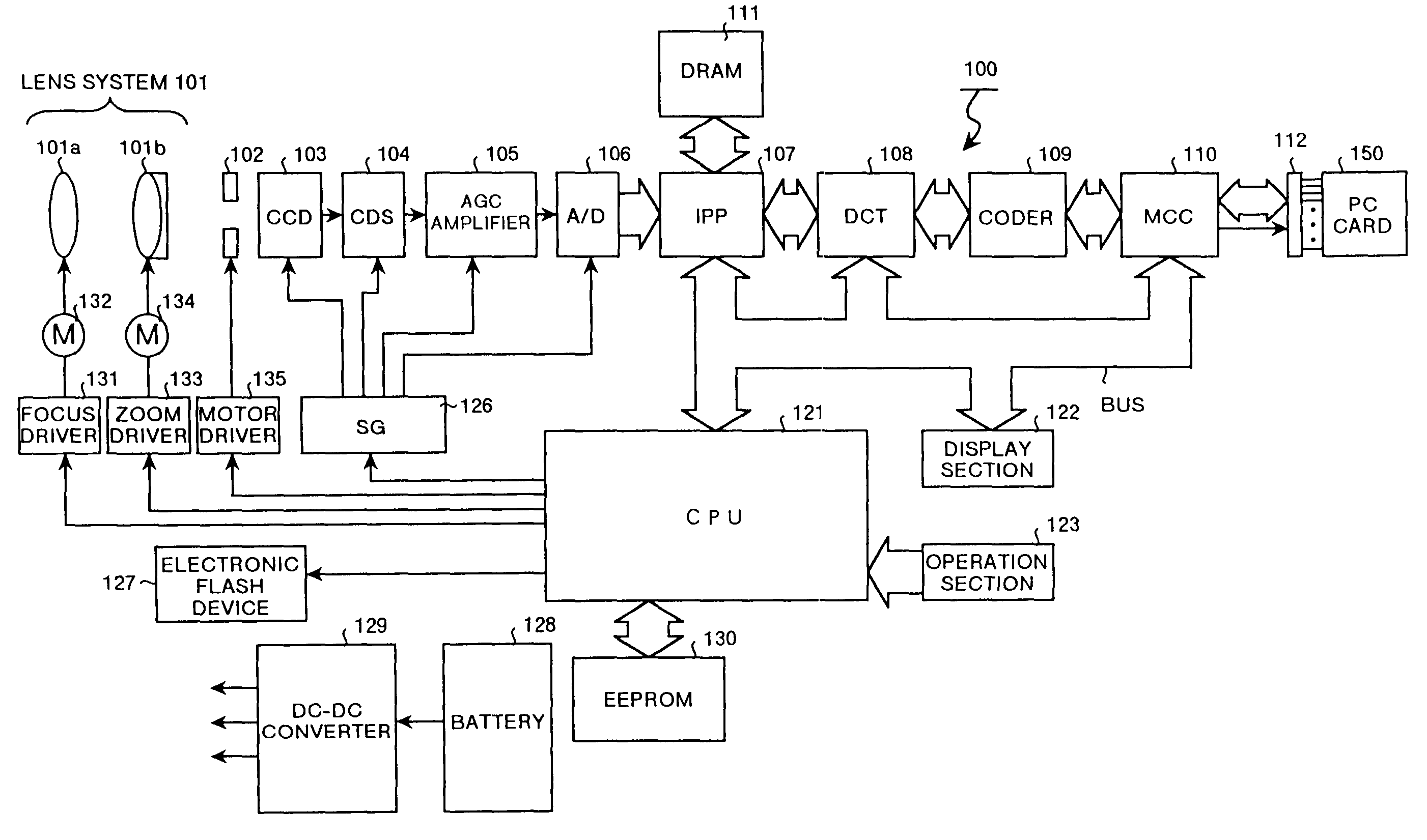
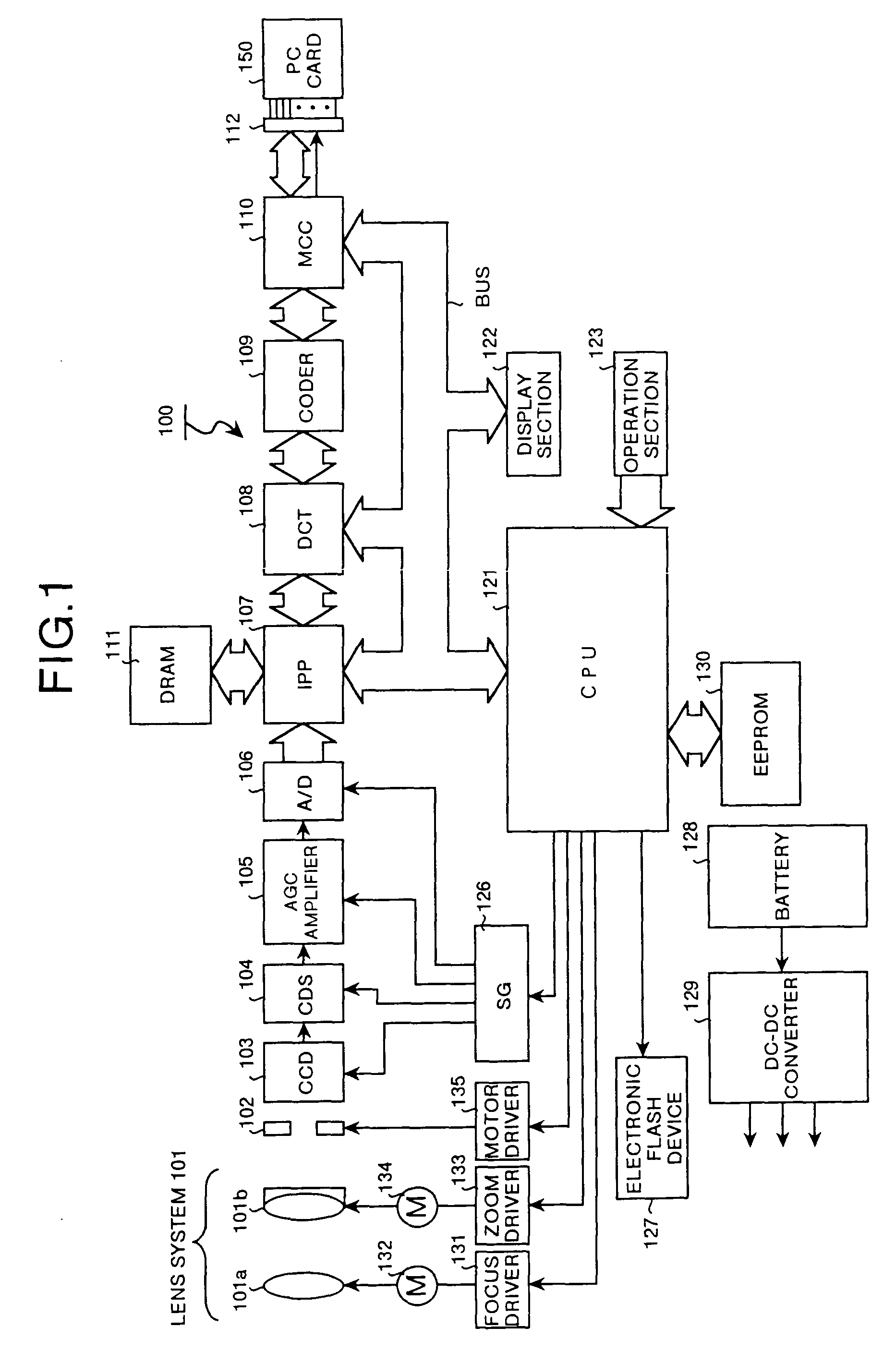
[0025]FIG. 1 is a block diagram showing a digital camera with an autofocus apparatus according to a preferred embodiment of the invention applied therein. In this figure, the reference numeral 100 indicates a digital camera. This digital camera 100 comprises a lens system 101, a mechanical system 102 including a diaphragm and a filter or the like, a CCD (Charge-Coupled Device) 103, a CDS (Correlation Dual Sampling) circuit 104, an automatic gain control amplifier (AGC amplifier) 105, an A / D converter 106, an IPP (Image Pre-Processor) 107, a DCT (Discrete Cosine Transform) 108, a coder 109, an MCC (Memory Card Controller) 110, a DRAM 111, a PC card interface 112, a CPU 121, a display section 122, an operating section 123, an SG (control signal generating) section 126, an electronic flash device 127 for flashi...


PUM


Abstract

The autofocus apparatus determines a focus position according to a result of sampling an AF evaluated value and drives a lens system to the focus position. This autofocus apparatus further performs a flash in synchronism with a sampling timing of an AF evaluated value.

Description

FIELD OF THE INVENTION[0001]The present invention relates to an autofocus apparatus. More particularly, this invention relates to an autofocus apparatus for a digital camera or a digital video camera.BACKGROUND OF THE INVENTION[0002]Various systems have conventionally been proposed for the autofocus apparatus. For example, in silver-salt cameras of single-lens reflex type, autofocusing (AF) that uses the phase difference detection method has been utilized in a many models.[0003]In the AF system using the phase difference detection method the outputs from an AF sensor and hence the distance between two images are different according to a status of proper focus, a status of forward-offset focus, and a status of backward-offset focus. Therefore, the lens is driven to obtain proper focus in such a way that the distance between the images becomes equal to a distance at the proper focus. Amount of movement of the lens, namely an amount of movement of the image surface is then calculated f...

Claims


Application Information

Patent Timeline
IPC IPC(8): H04N5/222G02B7/28G02B7/36G03B7/16G03B13/36H04N5/232
CPCH04N5/23212G02B7/28H04N23/671H04N23/673
Inventor HATA, DAISUKE
Owner RICOH KK
Why Eureka
Try Eureka