Mechanically strippable upcoated optical fiber

a technology of optical fiber and stripping, applied in the direction of optical fiber with multi-layer core/cladding, optical waveguide light guide, instruments, etc., can solve the problems of increasing the likelihood of damage to the optical fiber, affecting the performance affecting the quality of the optical fiber, so as to achieve low adhesion

Active Publication Date: 2007-11-13
CORNING OPTICAL COMM LLC
View PDF25 Cites 18 Cited by
  • Summary
  • Abstract
  • Description
  • Claims
  • Application Information

AI Technical Summary

Problems solved by technology

Optical waveguides are relatively fragile and can experience relatively high increases in optical attenuation when subjected to tensile, bending, or torsional stresses and / or strains.
However, there are applications that require stripping relatively long lengths of the buffer layer from the optical fiber and / or stripping the buffer layer in relatively cold environments.
Stripping several shorter lengths is a laborious and time-consuming process and increases the likelihood of damage to the optical fiber.
Likewise, stripping the buffer layer in cold environments may cause damage.

Method used


Image

  • Mechanically strippable upcoated optical fiber
  • Mechanically strippable upcoated optical fiber
  • Mechanically strippable upcoated optical fiber

Examples


Embodiment Construction

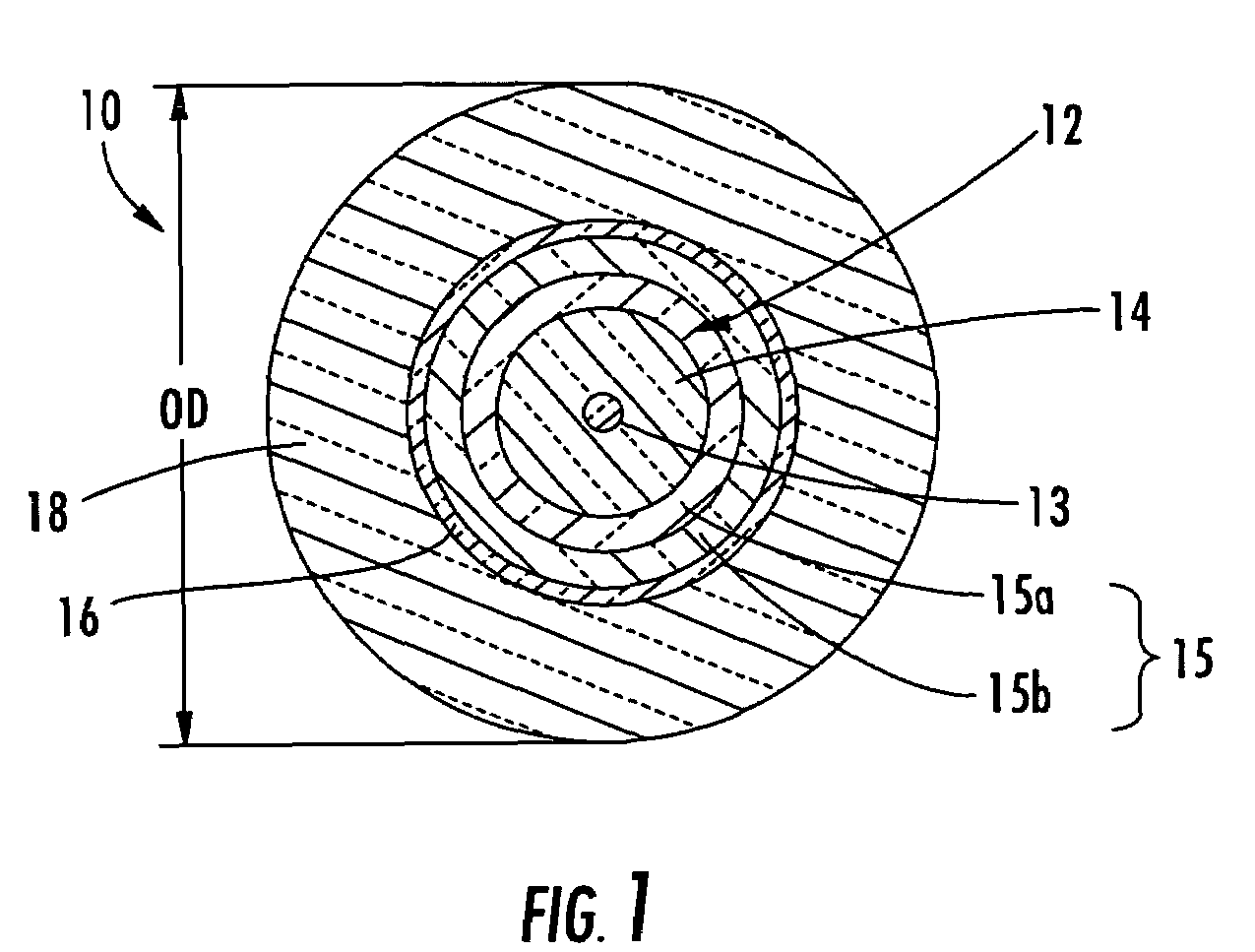
[0015]Reference will now be made in detail to the present preferred embodiments of the invention, an examples of which are illustrated in the accompanying drawings. Whenever possible, the same reference numerals will be used throughout the drawings to refer to the same or like parts. FIG. 1 depicts a cross-sectional view of an exemplary upcoated optical fiber 10 according to the present invention. Upcoated optical fiber 10 includes an optical fiber 12, a slip layer 16, and an upcoating 18 that is UV curable. As used herein, upcoated optical fiber refers to optical fibers having UV curable upcoating(s) that cross-link; rather, than a conventional plastic buffer layer such as a polyvinylchloride (PVC), polyethylene (PE) such as FRPE, or polypropylene (PP). As depicted, optical fiber 12 includes a core 13, a cladding 14, and at least one coating 15. In this case, coating 15 includes a primary coating 15a and a secondary coating 15b, which are applied during manufacturing of optical fib...


PUM


Abstract

An upcoated optical fiber includes an optical fiber having a ultra-violet (UV) curable upcoating and a slip layer disposed between the optical fiber and the upcoating. The upcoating is mechanically strippable from the optical fiber and may be colored for identification of the optical fiber. In one embodiment, the slip layer and upcoating both have predetermined glass transition temperatures that are within about 15° C. of each other for improving mechanical characteristics. The slip layer may be essentially the same color as the upcoating for identification of the optical fiber after the upcoating is removed or it may be uncolored. In suitable embodiments, the slip layer may include a micronized poly-tetra-fluoro-ethylene (PTFE), a silicone, and / or a dispersing agent for enhancing the strip performance of the upcoating over a range of temperatures.

Description

FIELD OF THE INVENTION[0001]The present invention relates generally to a robust upcoated optical fiber. More specifically, the invention is directed to an optical fiber further having a ultra-violet (UV) curable upcoated layer with a slip layer disposed between the optical fiber and upcoated layer for aiding the mechanically strippability of the upcoating.BACKGROUND OF THE INVENTION[0002]Optical waveguides such as optical fibers are used for transporting a variety of signals such as voice, video, data, and the like. Optical waveguides are relatively fragile and can experience relatively high increases in optical attenuation when subjected to tensile, bending, or torsional stresses and / or strains. Consequently, optical waveguides may include a buffer layer therearound for protecting the optical waveguide and preserving its optical performance. Additionally, buffer layers generally improve handlability of the relatively small diameter optical waveguides by increasing their diameter, t...

Claims


Application Information

Patent Timeline
Patent Type & Authority Patents(United States)
IPC IPC(8): G02B6/02
CPCG02B6/4495G02B6/4431
Inventor MOORJANI, SHAIL K.KOZAWA, YUTAKANISHIZAWA, KIYOFUMISUGIMOTO, MASHAHIDE
Owner CORNING OPTICAL COMM LLC
Why Eureka
Try Eureka