LED light bar assembly

a technology of led light bars and assembly parts, which is applied in the direction of lighting and heating apparatus, lighting heating/cooling arrangements, applications, etc., can solve the problems of low lumen, difficult to conceal fluorescent lamps, and light sources, and achieve the effect of strong illumination intensity

Inactive Publication Date: 2007-11-20
BEAUCHAMP PIERRE J
View PDF6 Cites 97 Cited by
  • Summary
  • Abstract
  • Description
  • Claims
  • Application Information

AI Technical Summary

Benefits of technology

[0006]It is a feature of the present invention to provide a lighting system for use in the above-mentioned applications and which does not generate intense heat and which provides a strong intensity of illumination.
[0007]Another feature of the present invention is to provide an LED (light emitting diode) light bar assembly which is miniature in size and which can easily be concealed.
[0008]Another feature of the present invention is to provide an LED (light emitting diode) light bar assembly which is easy to assemble and secure and wherein the light bulbs have a long life.
[0009]Another feature of the present invention is to provide an LED (light emitting diode) light bar assembly which is aesthetically pleasing, which has flexibility in that it can be provided in different lengths and which can be utilized in enclosed areas such as display cases.
[0011]Another feature of the present invention is to provide an LED (light emitting diode) light bar assembly which is easy to orient to direct the light beam at a desired location.

Problems solved by technology

However, these light sources have many disadvantages when used in these applications.
With these constraints, it is often difficult to conceal fluorescent lamps.
Another disadvantage of fluorescent lamps is that although they come in different lengths, the shorter the lamp, the lower is the lumen.
It is therefore difficult to use these lamps when a certain lumen is required and the mounting space is restricted.
Also, if two or more tubes are used, then dark spots will result between the zones between the fluorescent tubes.
The major disadvantage of halogen lamps is that they generate heat.
Accordingly, if these lamps are used in a constrained space, this heat needs to be taken into consideration as it could be damaging.
Another disadvantage of halogen lamps is that they have a relatively short life.
If these lamps are used in display cases, the heat can damage the articles being displayed.
Accordingly, these inconveniences limit the application of these lamps and they are mostly utilized in encapsulated housings mounted in ceilings of building structures and exposed to open spaces.
These encapsulated halogen lamps can be used in furniture cabinets provided that there are no products exposed to the lighting within ten inches thereof as the heat generated thereby will often cause discoloration of the articles.
They are also not recommended for use in enclosed display cases for jewelers as this heat will affect the lubricants in watches, for example.
Also because these lamps need to be periodically changed, they cause an inconvenience.
Still further, due to their sizes, they are difficult to conceal.

Method used


Image

  • LED light bar assembly
  • LED light bar assembly
  • LED light bar assembly

Examples


Embodiment Construction

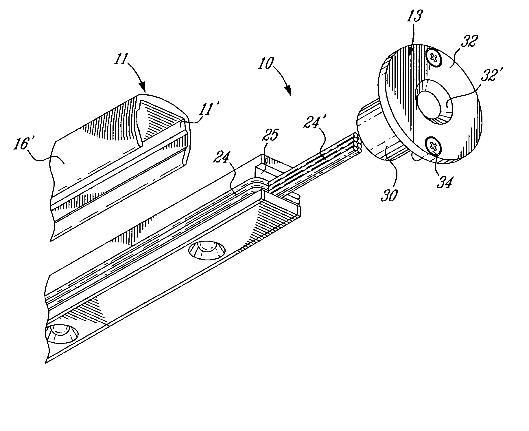
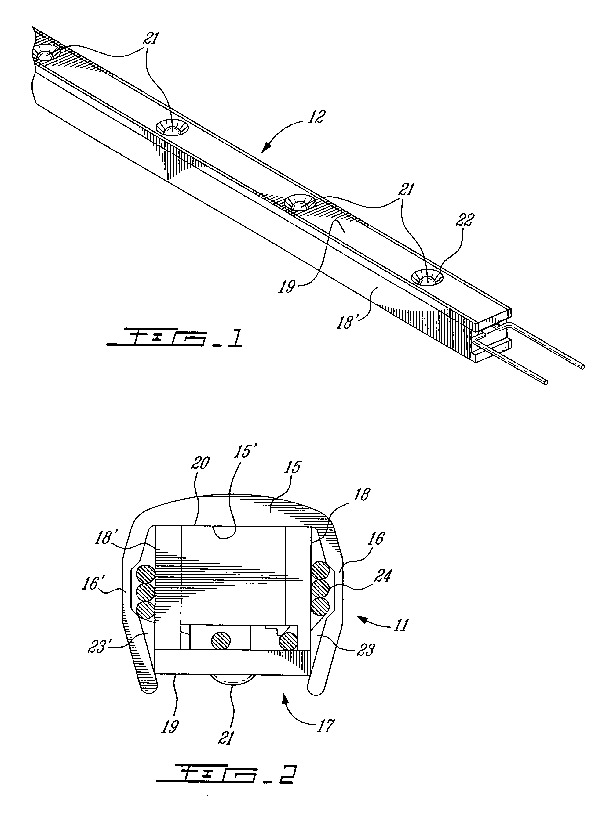
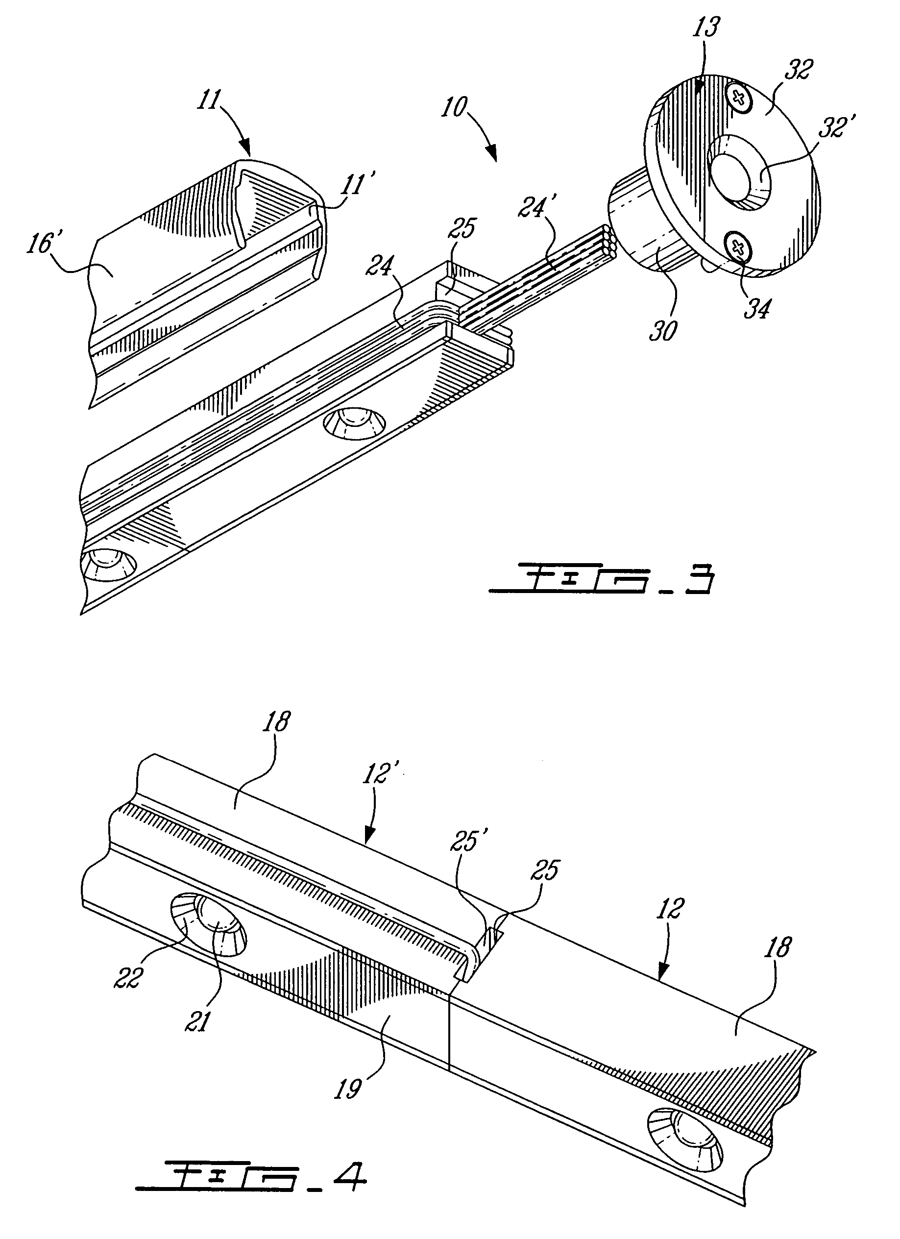
[0023]Referring now to the drawings and more particularly to FIGS. 1 to 5, there is shown generally at 10 in FIG. 3, the LED (light emitting diode) light bar assembly of the present invention. It is constituted by an elongated casing 11 which may be extruded from aluminum material or which may be formed of plastics, either extruded or molded, and in which there is slidingly retained one or more elongated heat sink LED modules 12, as shown in FIG. 1. The light bar assembly also comprises at least one end connector 13 which is detachably securable to an end of the casing 11 for securing the casing to a support structure 14, such as illustrated in FIG. 5, although it can be secured to various other types of support structures.

[0024]As shown in FIGS. 2 and 3, the elongated casing 11 has an elongated cavity 11′ which is substantially U-shaped in cross-section and defines a base wall 15, opposed side walls 16 and 16′ and an elongated open end 17. The side walls 16 and 16′ are inwardly cur...


PUM


Abstract

An LED (light emitting diode) light bar assembly is comprised of an elongated casing having an elongated cavity of substantially U-shape cross-section. The casing has a base wall, opposed side walls and an elongated open end between the side walls. One or more elongated heat sink LED modules each having two or more LEDs and electrical component parts thereof are retained in each of the modules. The LEDs are exposed in a spaced-apart relationship in a common wall of the modules. The casing is configured to removably receive and retain one or more of the modules therein in end-to-end relationship. The casing defines in combination with the one or more modules, at least one internal channel for the passage of wiring which is non-visible exteriorly of the module. At least one end connector is detachably securable to an end of the casing for securing the casing to a support structure. The connector has an internal passage for receiving wiring from the modules retained in the casing.

Description

TECHNICAL FIELD[0001]The present invention relates to an LED (light emitting diode) light bar assembly of miniature size and comprised essentially of an elongated casing in which are removably retained one or more elongated LED modules with the assembly being connectable to a support structure by at least one end connector. Preferably, but not exclusively, the light bar assembly is used in articles of furniture to provide a source of lighting which can easily be concealed.BACKGROUND ART[0002]Lighting systems used in articles of furniture such as display cases for jewelers, kitchen cabinets, gazebos and like applications where it is important to conceal the lights, utilize two common sources of lighting, namely fluorescent and halogen light sources. However, these light sources have many disadvantages when used in these applications. For example, when using fluorescent lighting, such usually requires additional wiring to bring in the standard 110 volt A.C. supply. It is also necessar...

Claims


Application Information

Patent Timeline
Patent Type & Authority Patents(United States)
IPC IPC(8): F21V21/00
CPCA47F3/001F21S4/008F21V33/0012Y10S362/80F21Y2101/02F21S4/28F21Y2115/10
Inventor BEAUCHAMP, PIERRE J
Owner BEAUCHAMP PIERRE J
Why Eureka
Try Eureka