
Weight interchangeable putter

a technology of weight and putter head, which is applied in the field of golf putter, to achieve the effect of reducing the twisting of the putter head and distributing the weight in the putter head

Active Publication Date: 2007-11-20
JUNG MAN YOUNG
View PDF7 Cites 84 Cited by
  • Summary
  • Abstract
  • Description
  • Claims
  • Application Information

AI Technical Summary

Benefits of technology

[0012]Therefore, when the screws are in their initial positions the putter with its face balanced neutralizes the leftward pulling or rightward pushing in the putting of the right-handed golfer who tends to show more pulling problems. At the same time, the double bend shaft mitigates the twisting of the putter head upon hitting the ball with its off center areas resulting in a widened sweet spot to give the right direction to the ball in more occasions.
[0014]Accordingly, the general object of the present invention is to provide a golf putter with speedy adjustment of the weight distribution in the head.Another object is to provide a golf putter having an alignment aid and weight-adjusting members which provide an extra visual aid as well as a structural indicator of the invisible sweet spot to improve the actual approach of the ball into the hole cup.

Problems solved by technology

Golf requires delicate control of a small 45-gram golf ball over a long distances with only a number of golf clubs.
In addition, individual peculiarity or habit of ball striking inevitably develops to lead the ball to all but the desired direction and speed.

Method used


Image

  • Weight interchangeable putter
  • Weight interchangeable putter
  • Weight interchangeable putter

Examples


Embodiment Construction

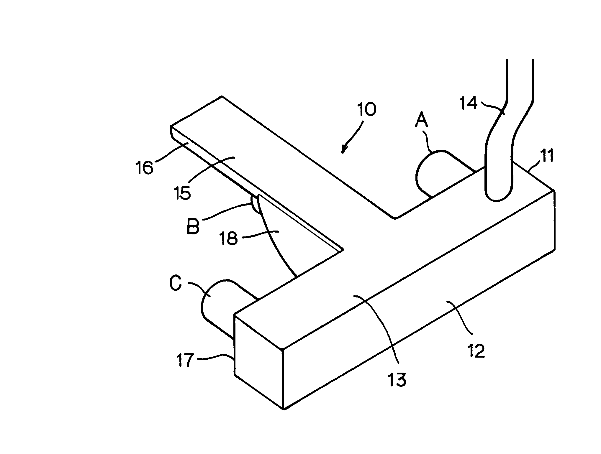
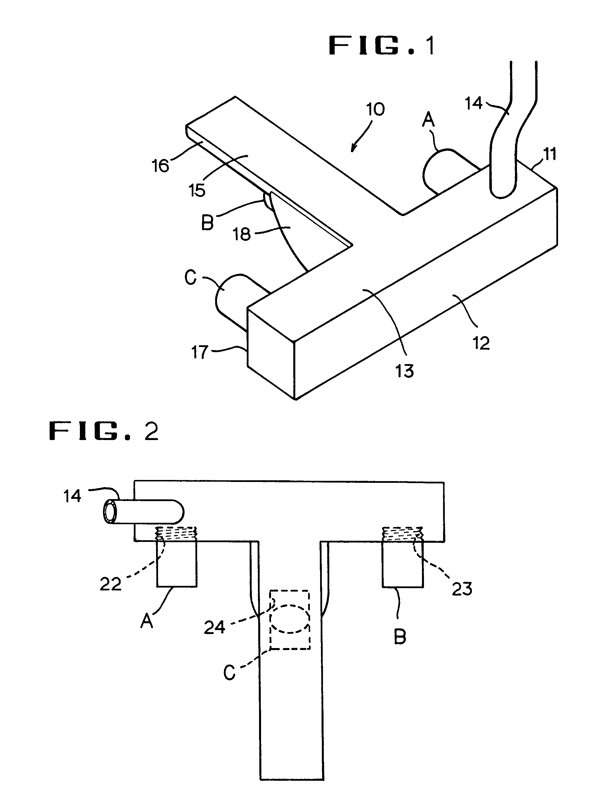
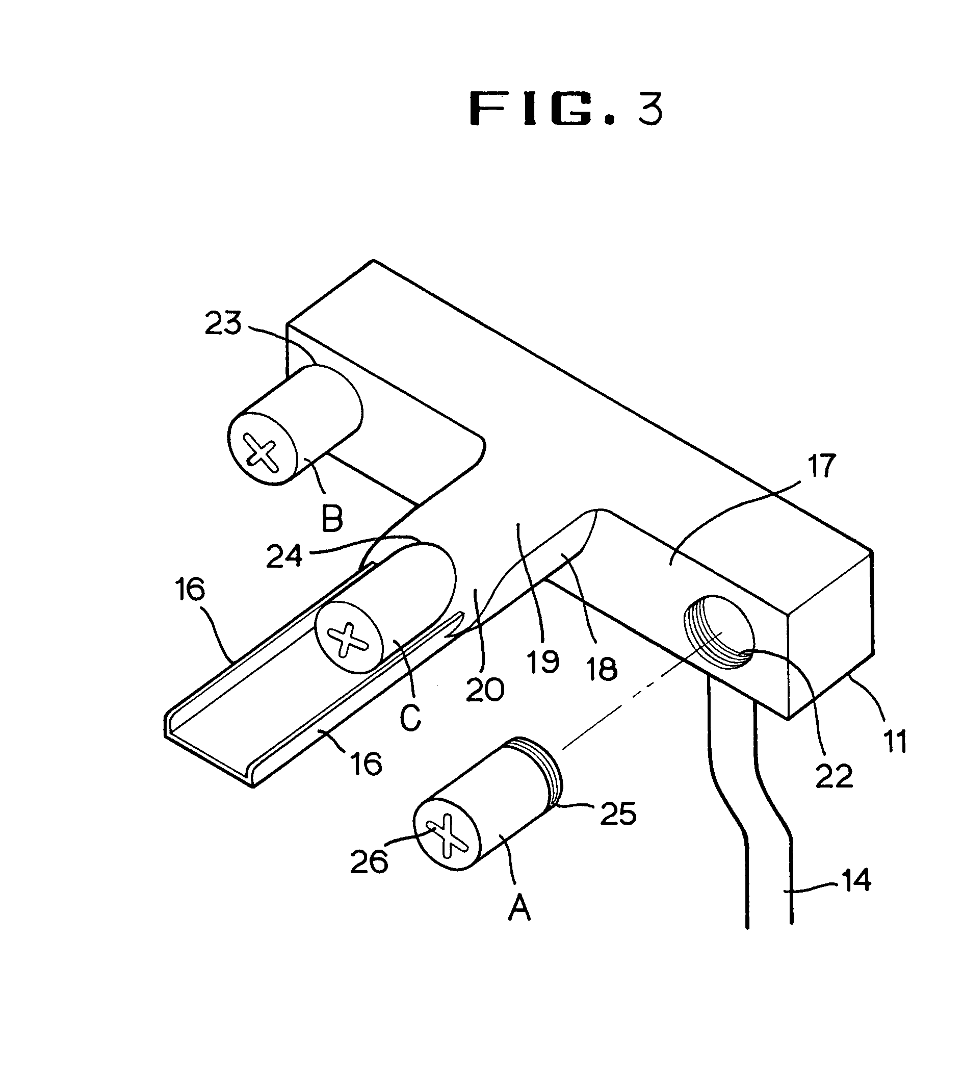
[0021]Referring to the drawings, the putter head of the present invention is generally denoted by 10 in the shape of a T. The head 10 has a main body 11 constituting the main weight and a striking face 12. Top surface 13 extends parallel to the ground and has an opening near its one end to accommodate a shaft 14 with a double bend leading to a grip for the golfer which is not shown. From the trailing edge of the top surface 13 a center tail 15 extends rearward to form the T shape of putter plane. At the sides of the tail 15 there are formed end fins 16 with their free ends opened rearward to better guide the putter head through the air during the stroking address. The center tail may be painted white to give a well-contrasted line in the green grass of the course.

[0022]Opposite of the face 12 is a rear wall 17 from which a back weight 18 branches centrally perpendicular to the main body 11. The top of the back weight 18 extends to near midway of the length of the tail 15 and merges ...


PUM


Abstract

A weight interchangeable golf putter is provided having a T shaped head. The head has a main body constituting the main weight and a striking face. From the trailing edge of the top surface a center tail extends rearward to form the T shape of putter plane. At the sides of the tail there are formed end fins with their free ends opened rearward to better guide the putter head through the air during the stroking address. The top of the back weight extends to near midway of the length of the tail and merges with the bottom of the tail. The back weight has a bottom surface in flush with the corresponding bottom of the main body and terminates with an end wall tapered gradually toward the main body to avoid hitting the ground when strokes are made. Three cylindrical bores are formed facing the same backward direction in the common 90-degree angle from the rear wall to receive different metal screws. When the screws are in their initial positions the putter with its face balanced neutralizes the leftward pulling or rightward pushing in the putting of the right-handed golfer who tends to show more pulling problems. Balance adjusting at the day's practice rounds or putting will be rightfully done with ease and no special tool thanks to the protruding screw design which provides an extra visual aid as well as a structural indicator of the invisible sweet spot to improve the actual approach of the ball into the hole cup.

Description

BACKGROUND OF THE INVENTION[0001]A. Field of the Invention[0002]The present invention relates to golf putters, and more particularly to a weight interchangeable putter structure.[0003]B. Description of the Prior Art[0004]Golf requires delicate control of a small 45-gram golf ball over a long distances with only a number of golf clubs. Golf becomes a precision game won by the player with the least total strokes. The golf club generally consists of a grip, a shaft and a head and is categorized into woods, irons and putters. Woods or irons are the suitable clubs for long distance shots while the putter is for green putting over most preferably one or two relatively short green distances.[0005]Typically, the putter head is designed to have an almost perpendicular clubface to the playing ground with a loft angle necessary to roll the ball. The shaft of the putter is distinctive from the other clubs in that it extends more upright from the head or has a higher lie angle allowing the playe...

Claims


Application Information

Patent Timeline
Patent Type & Authority Patents(United States)
IPC IPC(8): A63B53/00
CPCA63B53/0487A63B2209/00A63B2053/0491A63B2053/0441A63B53/0441A63B60/02
Inventor JUNG, MAN YOUNG
Owner JUNG MAN YOUNG
Learn More