Transmission apparatus

a technology of transmission apparatus and transmission shaft, which is applied in the direction of rotary clutches, fluid couplings, gearings, etc., can solve the problems of limited maximum transmission power and service life, difficult to apply toroidal-type cvt to a large equipment, and difficult to reduce the service life of toroidal-type cvt, which utilizes solid friction, etc., to achieve efficient transmission and increase the service life and power transmission limit

Inactive Publication Date: 2007-11-20
EBARA CORP
View PDF28 Cites 24 Cited by
  • Summary
  • Abstract
  • Description
  • Claims
  • Application Information

AI Technical Summary

Benefits of technology

[0011]The present invention has been made in view of the above drawbacks. It is therefore an object of the present invention to provide a transmission apparatus which can efficiently transmit a rotational power beyond a transmission limit of a joint unit, and can absorb various kinds of vibrations and impacts, such as pulsation, shock vibration at speed change, and torsion vibration of an output shaft, for thereby enabling an increase in service life and power transmission limit.
[0018]It is preferable that the fluid coupling comprises a variable-speed fluid coupling. According to the transmission apparatus of the present invention having such a structure, the rotational power beyond the transmission limit of the joint unit is not input to the joint unit, and hence the rotational power can be transmitted efficiently. Further, the fluid coupling can absorb various kinds of vibrations and impacts, such as pulsation of the input rotational power, shock due to speed change, and torsion vibration of the shaft, thus enabling a smooth transmission of the power.
[0030]Accordingly, since the power from the drive unit is transmitted to the load without passing through the joint unit, a capacity of the joint unit can be small even in a case of operating a large machinery. Further, since the joint unit comprises the differential planetary gear unit having no frictional part but having a mechanically coupling structure, the long service life can be achieved and the transmission limit can become sufficiently high.

Problems solved by technology

Since the toroidal-type CVT is of a contact type, there are limits to a maximum transmission power and a service life.
Therefore, it is difficult to apply the toroidal-type CVT to a large equipment which is required to transmit a large power, and to an industrial machinery which is required to have a reliability.
Accordingly, the toroidal-type CVT, which utilizes solid friction, is problematic in output fluctuation and durability because of such vibrations and impacts.
In addition, another type of conventional transmission apparatus has the same problems.

Method used


Image

  • Transmission apparatus
  • Transmission apparatus
  • Transmission apparatus

Examples


first embodiment

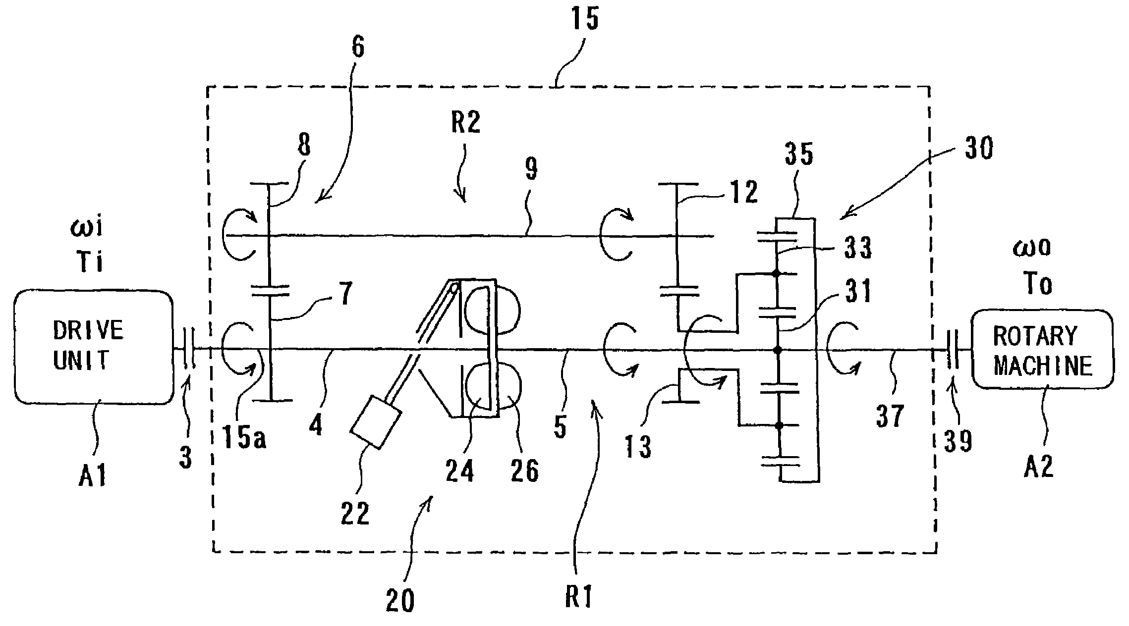
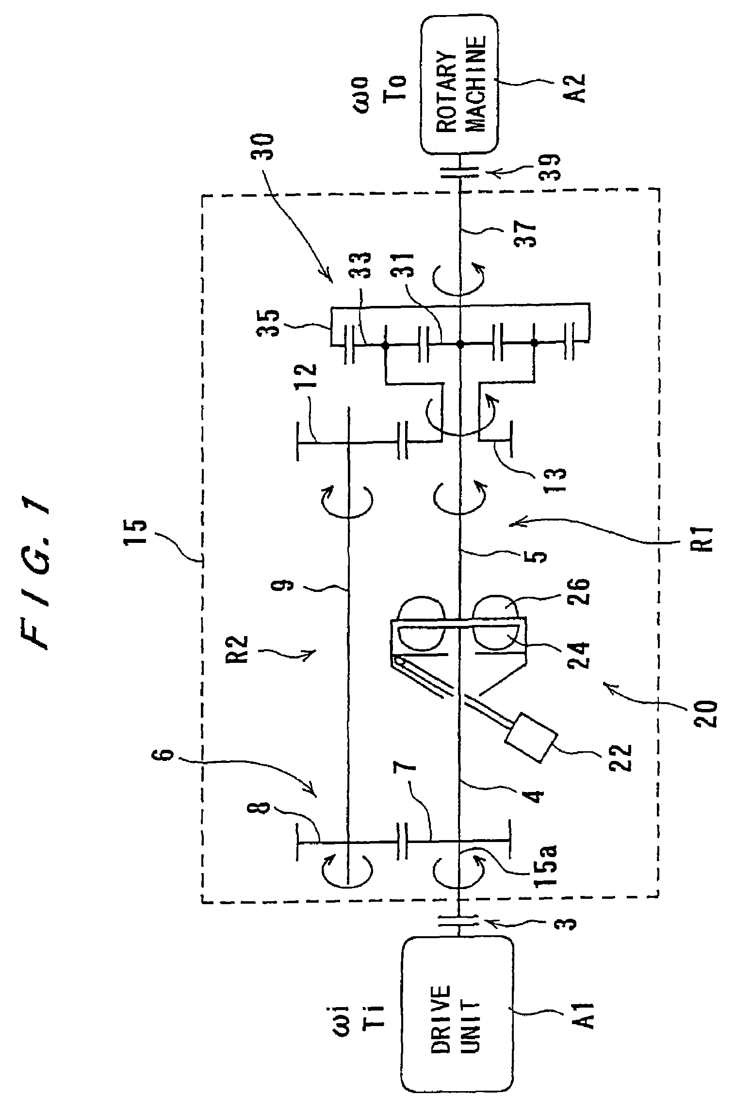
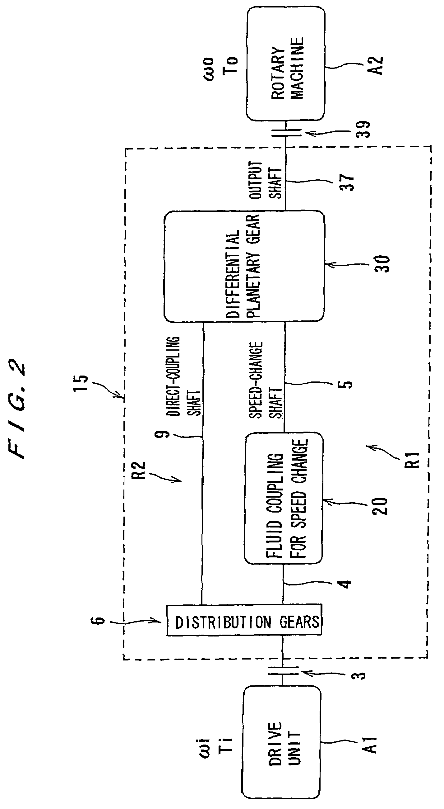
[0059]FIGS. 1 and 2 show the present invention. FIG. 1 is a schematic view showing a detailed structure of a transmission apparatus of the present invention, and FIG. 2 is a block diagram schematically showing the transmission apparatus. Those parts which are denoted by the same reference numerals as those of the conventional apparatus shown FIG. 23 have identical structure and function.

[0060]In FIGS. 1 and 2, a transmission apparatus 15 is disposed between a motor A1 (expressed as a drive unit A1 in FIG. 1) serving as a drive source and a fluid machinery A2 (expressed as a rotary machine A2 in FIG. 1) serving as a driven unit. The transmission apparatus 15 is coupled to the motor A1 and the fluid machinery A2 via an input-side clutch 3 and an output-side clutch 39.

[0061]The transmission apparatus 15 comprises a power-dividing unit 6, a fluid coupling 20 for speed change, and a differential planetary gear unit 30, each of which serves as an essential part thereof.

[0062]The power-div...

eighth embodiment

[0158]FIG. 12 shows an In FIG. 12, an output shaft 60 of a drive unit, e.g., an electric motor M, is coupled to a first gear 61 constituting a dividing unit 6. The first gear 61 is in mesh with a second gear 62 of the dividing unit 6.

[0159]The dividing unit 6 has a first output shaft 63 serving as a rotating shaft of the first gear 61. This first output shaft 63 is connected to a sun gear 64 of a second differential planetary gear unit P2. A carrier 66 of planetary gears 65 of the differential planetary gear unit P2 is coupled to a gear 67 meshing with a gear 68 that is coupled to an output shaft 69 of a small-capacity variable-speed motor 70. A ring gear 71 of the second differential planetary gear unit P2 is connected to an output shaft 72.

[0160]In this example shown in FIG. 12, the output shaft 60 of the drive unit M is connected to the sun gear 64 via the output shaft 63, and a rotational power of the variable-speed motor 70 is transmitted to the planetary gears 65. Although th...

ninth embodiment

[0165]FIG. 13 shows the present invention. An output shaft 60 of a drive unit M is connected to a first rotating element of a first differential planetary gear unit P1, and is also connected to a second rotating element, which mainly transmits a power, of the first differential planetary gear unit P1. A first output shaft 81 is a direct-coupling shaft and is connected to a second gear 82 of a converging unit 6B. A second output shaft 83, which is connected to a third rotating element of the first differential planetary gear unit P1, is a speed-change shaft and is connected to a first rotating element of the second differential planetary gear unit P2.

[0166]A second rotating element of this second differential planetary gear unit P2 is connected to an output shaft 69 serving as a motor shaft of a small-capacity variable-speed motor 70. Further, a third rotating element of the second differential planetary gear unit P2 is connected to a first gear 84 meshing with the second gear 82 of ...


PUM


Abstract

The present invention relates to a transmission apparatus (15) including at least one of a dividing unit (6) and a differential planetary gear unit (30), and a joint unit (20). A rotational power, which has been input to the transmission apparatus (15), is transmitted to the joint unit (20) via the dividing unit (6) or the differential planetary gear unit (30). A rotational power to be input to the joint unit (20) is smaller than the rotational power which has been input to the transmission apparatus (15), and the joint unit comprises a fluid coupling.

Description

TECHNICAL FIELD[0001]The present invention relates to a transmission apparatus having a dividing unit to which a rotational power from a drive unit is transmitted, a joint unit, and a first differential planetary gear unit, and specifically to a transmission apparatus used to rotate a fluid machinery such as a turbo machinery by a drive unit such as a motor for synchronizing a drive side and a driven side with each other, relieving an impact that occurs at starting / stopping or at changing in a rotational speed, and achieving an efficient transmission of a rotational power.BACKGROUND ART[0002]In a conventional apparatus shown in FIG. 22, an output shaft C4 of an electric motor A1 serving as a drive source is connected to an input side of a driven unit A2 such as a fluid machinery via a joint A22 and an output shaft C7. In this case, transmission of a rotational power from the electric motor A1 is limited to a range in which the joint A22 can transmit the rotational power.[0003]At the...

Claims


Application Information

Patent Timeline
Patent Type & Authority Patents(United States)
IPC IPC(8): F16H47/08F16H3/72
CPCF16D33/14F16H3/72F16H47/085F16H2037/088F16H2037/0866
Inventor KIMURA, KATSUMIMIWA, TOSHIOTAKASHIMA, MICHIOUSAMI, KENSUGIYAMA, KAZUHIKO
Owner EBARA CORP
Why Eureka
Try Eureka