
Ultrasound method and apparatus for multi-line acquisition

a multi-line acquisition and ultrasonic technology, applied in ultrasonic/sonic/infrasonic diagnostics, instruments, applications, etc., can solve the problem of increasing the cost of the interconnection infrastructure within the ultrasound system with data bandwidth

Active Publication Date: 2007-11-20
GE MEDICAL SYST GLOBAL TECH CO LLC
View PDF46 Cites 18 Cited by
  • Summary
  • Abstract
  • Description
  • Claims
  • Application Information

AI Technical Summary

Problems solved by technology

The cost of the interconnect infrastructure within the ultrasound system increases with data bandwidth, as more pins are required on integrated circuits for signal processing, more pins on circuit board connectors, or a faster clock rate of the data paths.

Method used


Image

  • Ultrasound method and apparatus for multi-line acquisition
  • Ultrasound method and apparatus for multi-line acquisition
  • Ultrasound method and apparatus for multi-line acquisition

Examples


Embodiment Construction

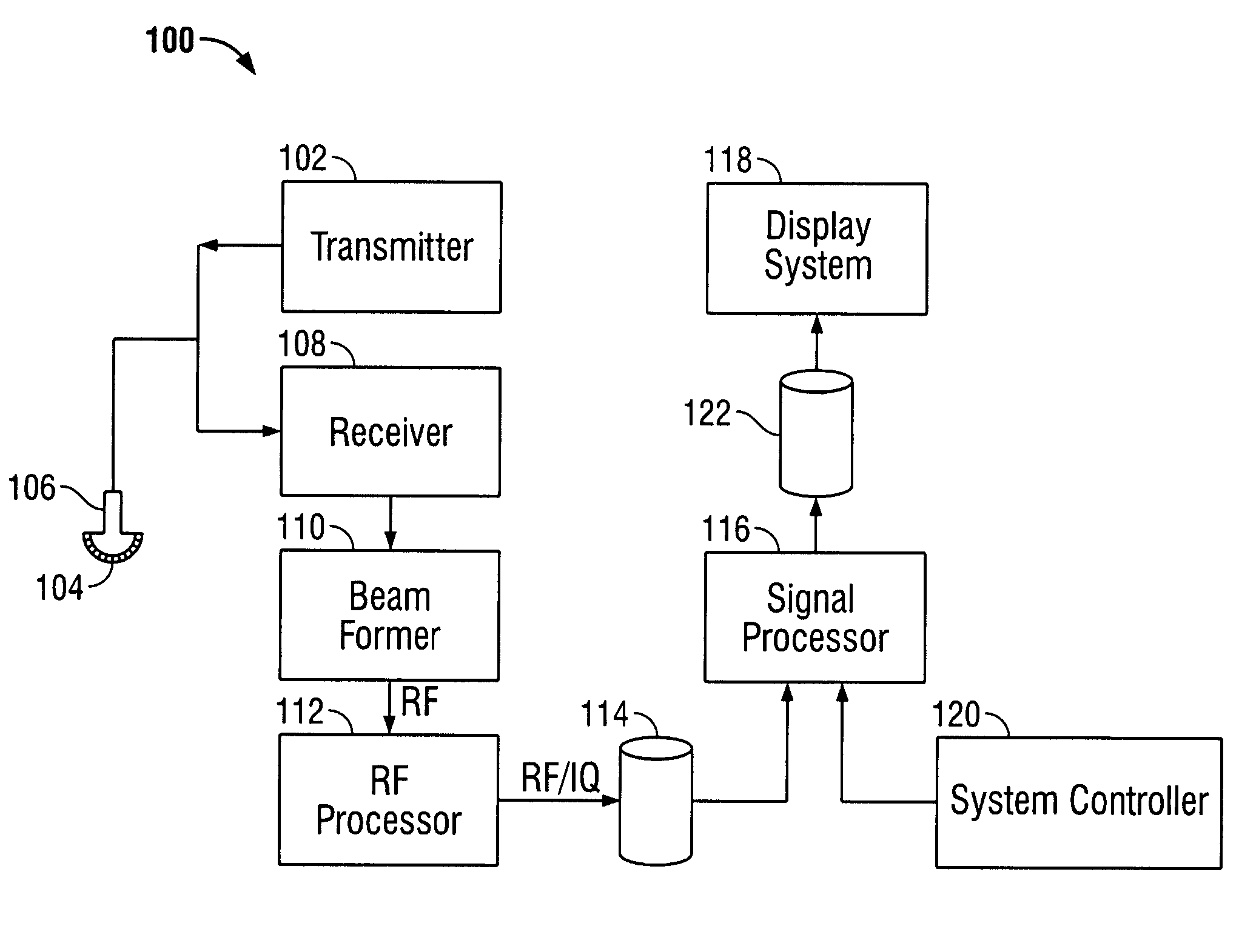
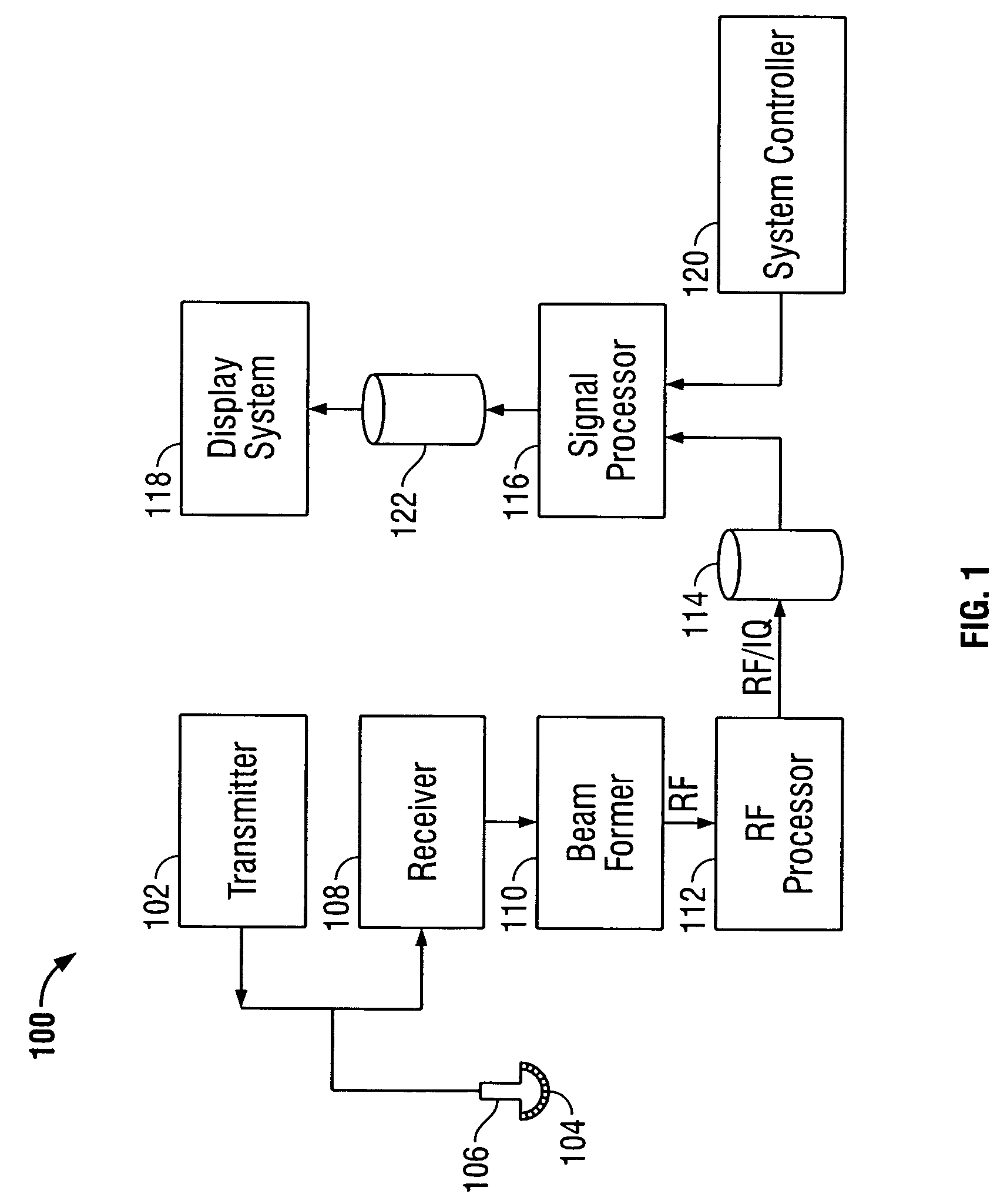
[0020]FIG. 1 illustrates a block diagram of an ultrasound system 100 formed in accordance with an embodiment of the present invention. The ultrasound system 100 includes a transmitter 102 which drives an array of elements 104 within a transducer 106 to emit pulsed ultrasonic signals into a body. A variety of geometries may be used. The ultrasonic signals are back-scattered from structures in the body, like blood cells or muscular tissue, to produce echoes which return to the elements 104. The echoes are received by a receiver 108. The received echoes are passed through a beamformer 110, which performs beamforning and outputs an RF signal. The RF signal then passes through an RF processor 112. Alternatively, the RF processor 112 may include a complex demodulator (not shown) that demodulates the RF signal to form IQ data pairs representative of the echo signals. The RF or IQ signal data may then be routed directly to RF / IQ buffer 114 for temporary storage. A system controller 120 cont...


PUM


Abstract

A method and apparatus for acquiring multi-line acquisition ultrasound data. Ultrasound signals are transmitted into an area of interest. Echo signals are acquired and analyzed to produce a first data stream associated with a first receive beam. The first data stream is decimated by removing at least two consecutive data samples therefrom, while passing at least two consecutive data samples to form a first decimated data stream. Using this decimation pattern, a bandwidth of one-half to three-quarters of the data sampling rate after decimation may be achieved.

Description

CROSS REFERENCE TO RELATED APPLICATION[0001]The application relates to and claims priority from provisional patent application Ser. No. 60 / 477,826, titled “Ultrasound Method and Apparatus for Multi-Line Acquisition”, filed Jun. 12, 2003, the complete subject matter of which is expressly hereby incorporated herein in its entirety.BACKGROUND OF THE INVENTION[0002]The present invention relates to diagnostic ultrasound systems. In particular, the present invention relates to method and apparatus for acquiring and processing ultrasound data streams to reduce the bandwidth of the data without deteriorating the performance of the beamformer, and to share the bandwidth between two or more data streams belonging to different beams in multi-line acquisition.[0003]FIG. 3 illustrates a typical configuration of a receive beamformer 200. Digitized channel signals are input to a number of identical signal processing devices (beamformer ASICs) 202-206, that are interconnected in a beamsum pipeline....

Claims


Application Information

Patent Timeline
Patent Type & Authority Patents(United States)
IPC IPC(8): A61B8/00G01S7/52G01S15/89G10K11/34H04R3/00H04R17/00
CPCG01S7/52034G01S15/8993G01S7/52095
Inventor KRISTOFFERSEN, KJELL
Owner GE MEDICAL SYST GLOBAL TECH CO LLC
Learn More