Method of determining measurement bias in an emissions monitoring system

a technology of emissions monitoring and measurement bias, applied in the field of measurement of air poll, can solve the problems of preventing these systems from meeting the accuracy requirements, system subject to a number of sources of bias, etc., and achieve the effect of minimizing bias

Inactive Publication Date: 2007-11-20
GENERAL ELECTRIC CO
View PDF12 Cites 11 Cited by
  • Summary
  • Abstract
  • Description
  • Claims
  • Application Information

AI Technical Summary

Benefits of technology

[0006]There is accordingly a need for a CEMS that minimizes bias in the measurement of emission constituent concentration levels generally and NOx concentration levels in particular. There is also a need for a CEMS that provides for routine monitoring of the remaining bias in the system.
[0009]One aspect of the invention provides an emissions monitoring system for monitoring constituent concentration levels in an emission stream flowing through a combustion source exhaust stack. The system comprises a sampling device configured and positioned for extraction of sample gas from the emission stream in the stack. A chamber is positioned adjacent the stack, the chamber defining a chamber interior. A chamber heater is disposed in the chamber interior. The system further comprises at least one sample gas line in fluid communication with the sampling device. At least a portion of the sample gas line is disposed in the chamber interior. A filter is disposed adjacent the stack, the filter being in fluid communication with the at least one sample gas line so that the sample gas passes through the filter. The filter removes particulate matter from the sample gas to produce a filtered sample gas. The system also includes a dryer disposed adjacent the chamber. The dryer is in fluid communication with the at least one sample gas line and has a dryer intake for receiving the filtered sample gas and a dryer exit for returning dried filtered sample gas to the at least one sample gas line. The dryer is configured for removing water from the filtered sample gas and for effectively lowering the dew point of the filtered sample gas. The system also comprises at least one analyzer in fluid communication with the at least one sample gas line. Each of the at least one analyzer is configured for determination of a concentration level of a constituent in the dried filtered sample gas.

Problems solved by technology

Current CEMS systems are subject to a number of sources of bias with respect to NOx measurement.
Bias effects in the systems now in use may prevent these systems from meeting the accuracy requirements that go along with the measurement of smaller concentrations.

Method used


Image

  • Method of determining measurement bias in an emissions monitoring system
  • Method of determining measurement bias in an emissions monitoring system
  • Method of determining measurement bias in an emissions monitoring system

Examples


Embodiment Construction

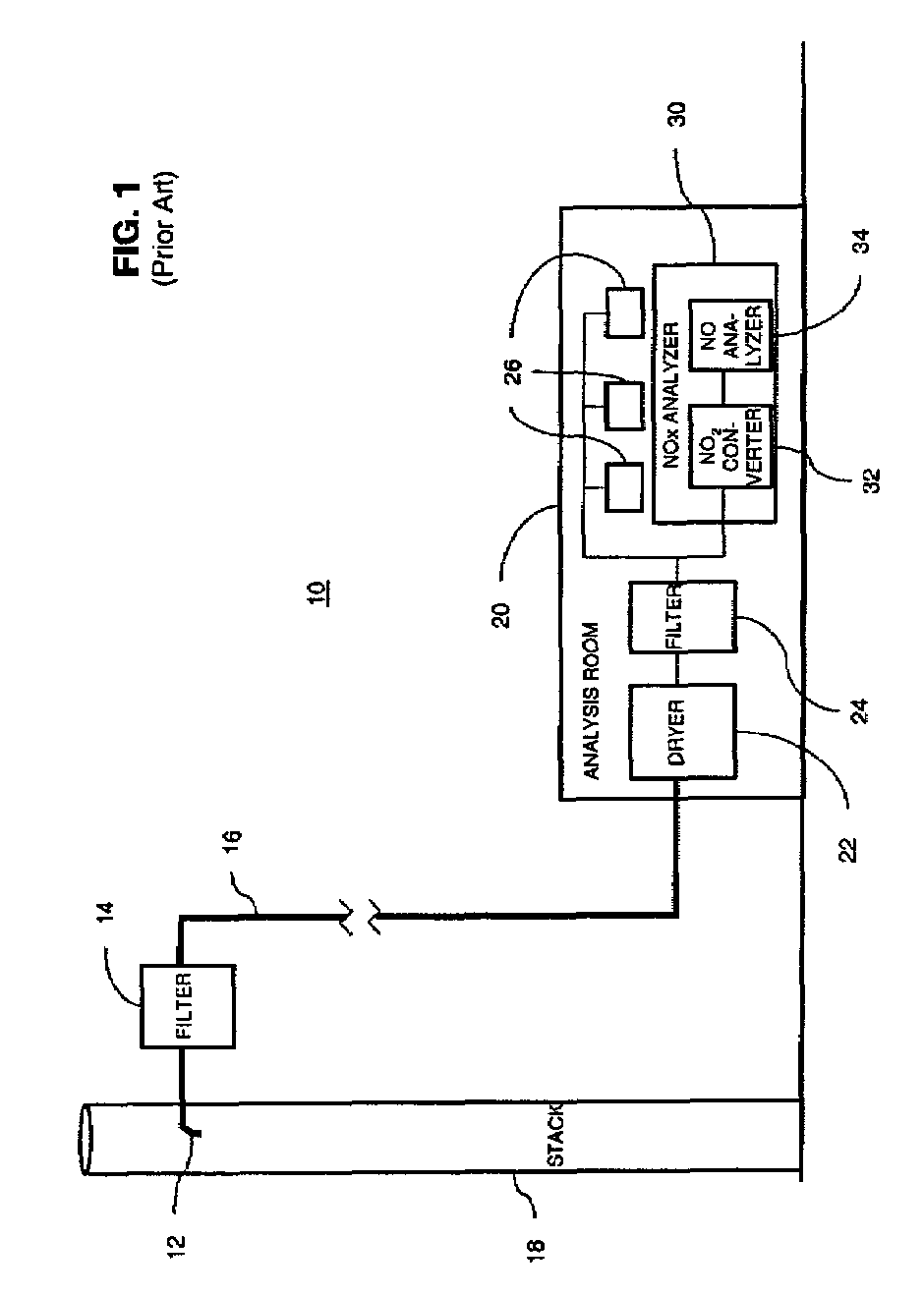
[0020]The present invention provides an emissions monitoring system that minimizes bias effects in the capture and analysis of NOx emissions. The invention also provides a method for routinely monitoring the system to identify changes in measurement bias. FIG. 1 is a schematic illustration of a typical prior art emissions monitoring system 10. In the system 10, multiphase exhaust emissions are drawn from a stack 18 using a sampling device 12. At the outlet of the sampling device 12, the emissions are passed through a filter 14 to remove large particulate matter on the order of 7 microns or greater.

[0021]The resulting sample gas and any remaining particulate matter are then passed through a heated sampling line 16 to a CEMS analysis room 20. The analysis room 20 is typically a small ground level building, trailer or mobile sampling van that houses the analyzers for the various types of emissions that must be assessed. Such a building is typically carefully climate controlled. Upon en...


PUM

PropertyMeasurementUnit
temperatureaaaaaaaaaa

Abstract

A method of determining bias in a measurement of a constituent concentration level in a sample gas is provided. The method comprises establishing a sample gas flow from an emission stream into a sample gas line of an emissions monitoring system. The method further comprises removing water from the sample gas flow and cooling the sample gas flow to a temperature below about 41° F. to produce a cooled, dried sample gas flow. The constituent concentration level is then determined for the cooled, dried sample gas flow. The method further comprises introducing a span gas having a known span gas constituent concentration level into the sample gas flow to form a combined sample and span gas flow, the span gas being introduced at a desired span gas flow rate. The method still further comprises removing water from the combined sample and span gas and cooling the combined sample and span gas to a temperature below about 41° F. to produce a cooled, dried, combined sample and span gas flow. A combined sample and span gas constituent concentration level is then determined for the cooled, dried, combined sample and span gas flow. The method also comprises determining a measurement bias using the known span gas constituent concentration level, the sample gas constituent concentration level and the combined sample and span gas constituent concentration level.

Description

[0001]This application is a continuation of prior application Ser. No. 09 / 682,900 filed Oct. 31, 2001 now U.S. Pat. No. 7,029,920.BACKGROUND OF THE INVENTION[0002]This invention relates to the measurement of air pollutant emissions from gas turbines, boilers, process heaters, furnaces and other combustion sources. More particularly, the invention relates to a continuous emission monitoring method and system that minimizes bias in the measurement of air pollutant emissions.[0003]Power plants and other users of combustion sources such as gas-fired turbines are required to keep emissions of certain exhaust constituents at or below specified levels. Continuous emission monitoring systems (CEMS) are required in order to assure on a continuous basis that the mandated levels are maintained. Over time, however, improved methods of minimizing emissions have evolved and emissions standards have become more stringent. CEMS systems are therefore required to consistently measure lower and lower ...

Claims


Application Information

Patent Timeline
Patent Type & Authority Patents(United States)
IPC IPC(8): G01N1/00B32B27/04B32B5/02G01N1/10G01N1/22G01N1/24G01N21/35G01N21/85G01N33/00
CPCG01N1/2258G01N33/0037Y10T436/255G01N2001/2261G01N2001/227Y10T436/177692Y10T436/186Y10T436/25125Y10T436/17Y10T436/207497Y10T436/204998Y10T436/25Y10T436/20Y10T436/25375Y10T436/208339Y10T436/178459Y10T436/25875Y10T436/205831Y10T436/179228G01N1/24Y02A50/20
Inventor LANIER, WILLIAM STEVENENGLAND, GLENN
Owner GENERAL ELECTRIC CO
Why Eureka
Try Eureka