Immunoassay system

Inactive Publication Date: 2007-11-20
MICRODIAGNOSTICS
View PDF29 Cites 8 Cited by
  • Summary
  • Abstract
  • Description
  • Claims
  • Application Information

AI Technical Summary

Benefits of technology

[0015]On the other hand, if the sample contains an amount of drug/metabolite above predetermined cut-off levels, such drug/metabolite will necessarily compete with the tracer and thus prevent the latter from binding to the antibodies. As a consequence, a portion of the tracer will be unable to bind to the antibodies and thus no visual signal will be generated thereby. Accordingly, the immunoassay system of the present invention will provide a signal in the absence of the target drug/metabolite sought to be detected, but will not provide such a signal should the same be present.
[0016]On average, the test takes approximately ten minutes or less to perform. As discussed above, to ensure accuracy, the immunoassay of the present invention may preferably be provided with a second stripe or zone of control antibodies specific to a second, unrelated tracer or label that is designed to provide a visual indication in every instance, preferably in the form of a control band, where a respective test st

Problems solved by technology

Early immunoassays required tedious manual steps and long incubation times, typically lasting for several hours.
While today's rapid competitive immunoassays are considered generally effective, such assay methods continue to suffer from significant drawbacks.
Moreover, because the re

Method used


Image

  • Immunoassay system
  • Immunoassay system

Examples


Embodiment Construction

[0020]The detailed description set forth below in connection with the appended drawings is intended merely as a description of the presently preferred embodiment of the invention, and is not intended to represent the only form in which the present invention may be constructed or utilized. The description sets forth the functions and sequence of steps for construction and implementation of the invention in connection with the illustrated embodiments. It is to be understood, however, that the same or equivalent functions and sequences may be accomplished by different embodiments that are also intended to be encompassed within the spirit and scope of the invention.

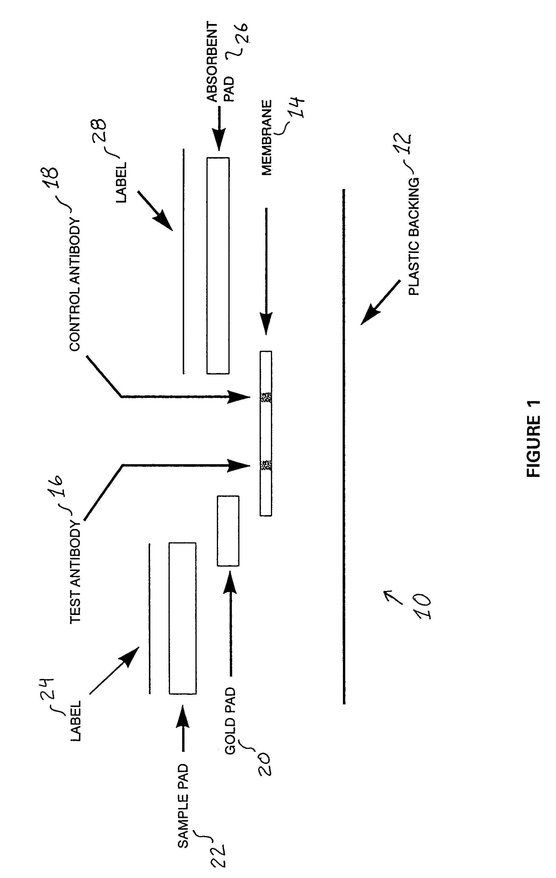
[0021]Referring now to the drawings, and initially to FIG. 1, there is schematically depicted the various components comprising an immunoassay 10 constructed in accordance with a preferred embodiment of the present invention. As illustrated, the immunoassay 10 comprises a plastic backing 12 upon which are formed the various o...


PUM

PropertyMeasurementUnit
Fluorescenceaaaaaaaaaa

Abstract

A competitive immunoassay, dye and method for rapidly detecting the presence of one or more target ligands within a fluid sample suspected of containing such ligand or ligands. The immunoassay comprises a protein-binding membrane, a first absorbent pad, a second absorbent pad, and a third absorbent pad. The protein-binding membrane has at least two regions of antibodies bound thereto for detecting dissimilar ligands. The second absorbent pad has formed therein a colloidal gold tracer having one, and preferably two or more ligand analog protein complexes adhering thereto. To utilize the system, the immunoassay strip is placed within a fluid sample. To the extent the target ligand is absent, a visual indicator will be provided signaling such absence. To the extent the target ligand is present at or above a threshold level, no such visual signal will be produced.

Description

CROSS-REFERENCE TO RELATED APPLICATIONS[0001]The present application is a continuation-in-part of U.S. patent application Ser. No. 09 / 813,071, filed Mar. 20, 2001, now abandoned entitled IMPROVED IMMUNOASSAY SYSTEM, which was a continuation of U.S. patent application Ser. No. 09 / 295,847 filed Apr. 21, 1999, now abandoned entitled IMPROVED IMMUNOASSAY SYSTEM, which is a continuation of U.S. patent application Ser. No. 09 / 195,309 filed on Nov. 18, 1998, now U.S. Pat. No. 6,480,310 entitled IMPROVED IMMUNOASSAY SYSTEM.STATEMENT RE: FEDERALLY SPONSORED RESEARCH / DEVELOPMENT[0002]Not ApplicableBACKGROUND OF THE INVENTION[0003]The present invention is directed to improved methods and immunoassays for detecting two or more ligands in a liquid sample suspected of containing such ligands, and more particularly, improved methods and immunoassays for rapidly and qualitatively detecting the presence or absence of one or more ligands via a single, rapid, competitive ligand-receptor reaction.[0004...

Claims


Application Information

Patent Timeline
IPC IPC(8): G01N33/52G01N33/558
CPCG01N33/558Y10S435/969Y10S436/823Y10S435/973
Inventor CHUNG, ROYSHOZI, JUNE
Owner MICRODIAGNOSTICS
Why Eureka
Try Eureka