
Crystal unit

a crystal unit and crystal structure technology, applied in piezoelectric/electrostrictive device details, piezoelectric/electrostrictive/magnetostrictive devices, oscillator generators, etc., can solve the problems of holding state and non-uniform vibration characteristic of the crystal unit, and achieve satisfactory quality and quality stability.

Inactive Publication Date: 2007-11-20
NIHON DEMPA KOGYO CO LTD
View PDF10 Cites 13 Cited by
  • Summary
  • Abstract
  • Description
  • Claims
  • Application Information

AI Technical Summary

Benefits of technology

[0011]It is an object of the present invention to provide a crystal unit whose vibration characteristic is maintained satisfactorily and has of stable quality.
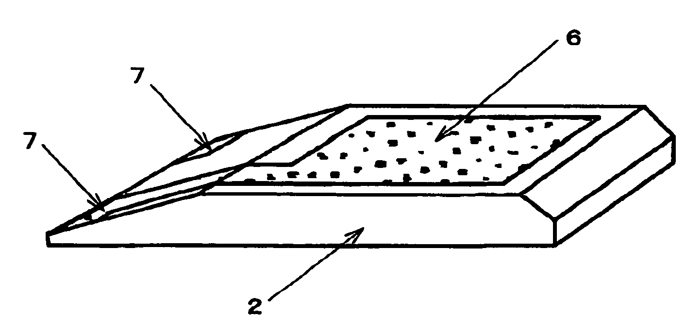
[0013]According to the present invention, when the crystal blank is fixed to the mounting member, the flat area of the crystal blank contacts the conductive material represented by the conductive adhesive. This allows pressing conditions such as the pressing force and pressing direction of a pressure applied to the crystal blank and conductive material to be controlled so that they are kept constant, and the crystal blank can be held uniformly and the quality of the finished crystal unit can also be stabilized. It further prevents a conductive adhesive or the like from wrapping around up to the vibration area of the crystal blank and keeps the vibration characteristic satisfactorily.

Problems solved by technology

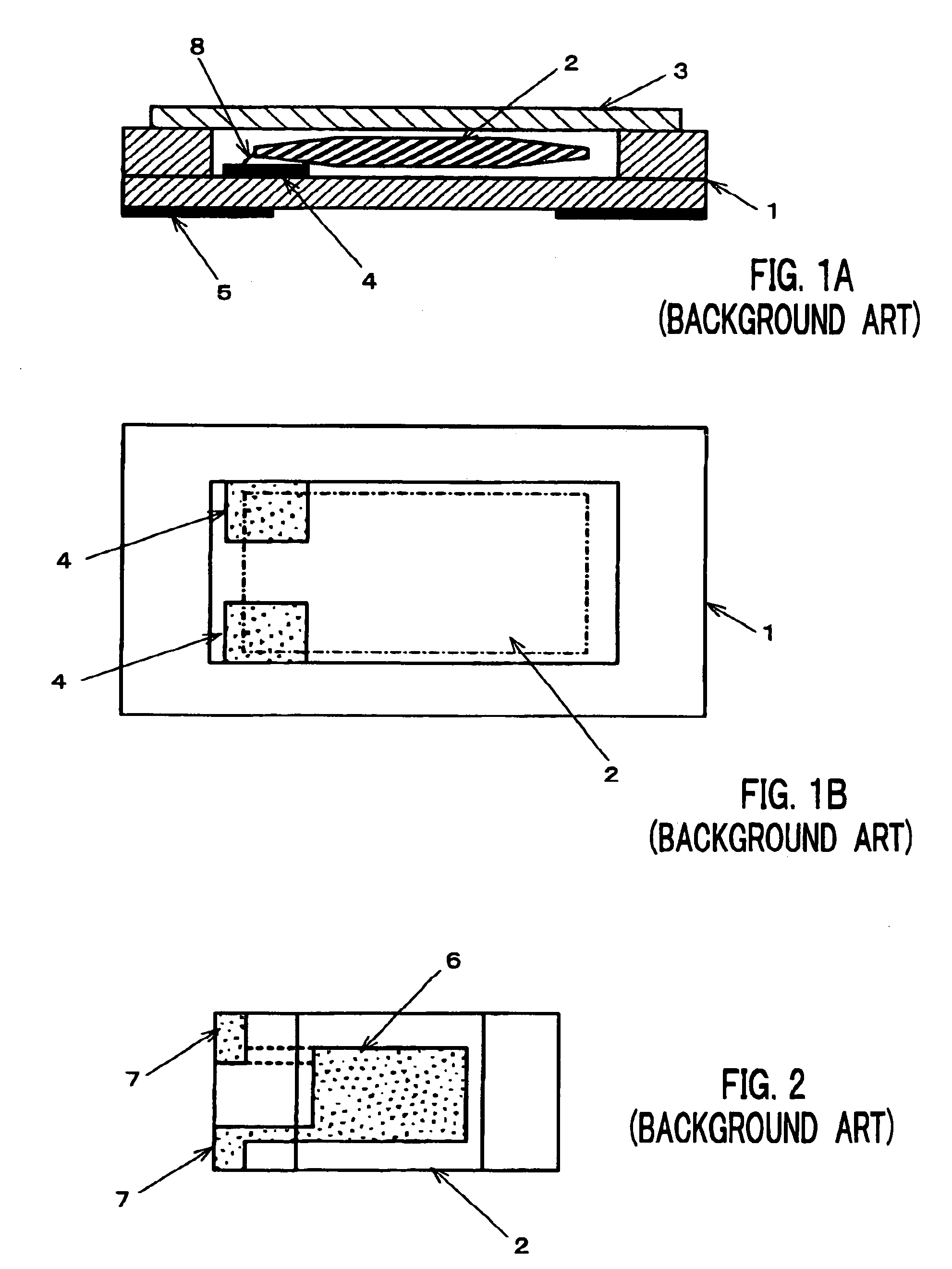
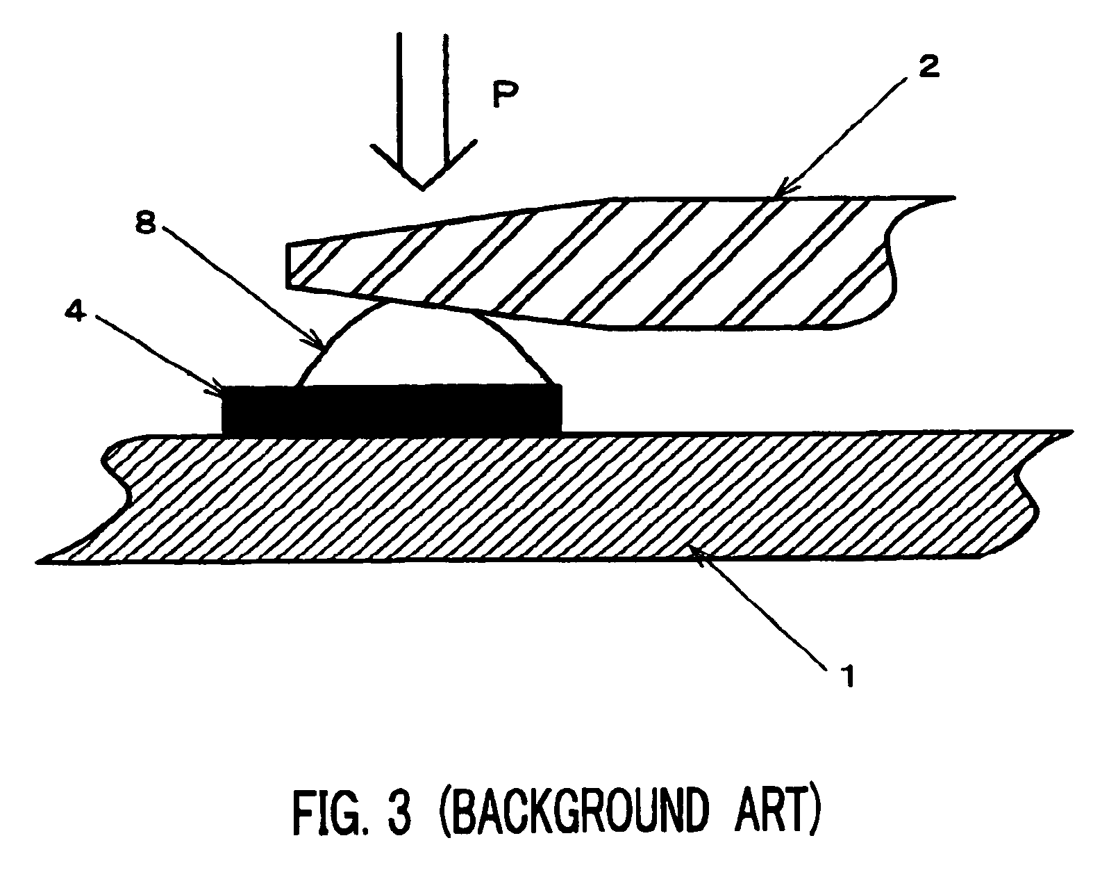
However, the surface mount crystal unit in the above described conventional configuration has the following problems because the inclined surfaces of the crystal blank are fixed by means of conductive adhesive 8.
With such variations in the pressing force and pressing direction, the holding state and holding system also vary from one crystal blank 2 to another, causing variations in the holding state and thereby producing also non-uniformity in the vibration characteristic as the crystal unit.
These problems become noticeable because the influence of holding crystal blank 2 increases as the miniaturization of crystal blank 2 advances.

Method used


Image

  • Crystal unit
  • Crystal unit
  • Crystal unit

Examples


Embodiment Construction

[0024]As in the case of the quartz crystal unit shown in FIGS. 1A and 1B, the crystal unit according to an embodiment of the present invention shown in FIG. 4 is realized by accommodating quartz crystal blank 2 in casing 1 made of laminated ceramics, covering the opening of casing 1 with cover 3 and thereby hermetically sealing crystal blank 2 in casing 1. As casing 1 used as the mounting member, a casing similar to that shown in FIGS. 1A and 1B is used, a pair of connection terminals 4 is provided on th bottom face of a recess of casing 1 and external terminals 5 electrically connected to connection terminals 4 are provided on the outer surface of casing 1.

[0025]As shown in FIG. 5, crystal blank 2 has a substantially rectangular shape as a two-dimensional projected shape and comprises, for example, an AT-cut quartz crystal blank. An AT-cut quartz crystal blank has a vibration mode by thickness-shear vibration. Crystal blank 2 has a first principal surface and a second principal sur...


PUM


Abstract

A crystal unit has a crystal blank provided with a pair of excitation electrodes and a pair of extension electrodes extended from the excitation electrodes, and a casing having a recess. A pair of connection terminals is formed on the bottom face of the recess. An inclined surface is formed at one end of a first principal surface of the crystal blank and the second principal surface of the crystal blank is flat-shaped. A conductive material is disposed between the connection terminals and the extension electrodes so that the extension electrodes are extended toward the end at which the inclined surface is formed and the second principal surface faces the mounting member, and the crystal blank is thereby held by the mounting member at the position of the end at which the extension electrodes are extended and electrically connected to the connection terminals.

Description

BACKGROUND OF THE INVENTION[0001]1. Field of the Invention[0002]The present invention relates to a quartz crystal unit, and more particularly, to a crystal unit having an excellent vibration characteristic and small dispersion in quality.[0003]2. Description of the Related Arts[0004]A surface mount crystal unit is widely used for an oscillator and the like as a reference source of frequency or time, especially in portable electronic devices since it is small and light. While miniaturization of a surface mount crystal unit is advancing more and more in recent years, the vibration characteristic of a crystal unit is required to be kept constant despite the miniaturization.[0005]A conventional surface mount crystal unit shown in FIGS. 1A and 1B is realized by accommodating quartz crystal blank 2 in casing 1 made of laminated ceramics or the like, covering the opening of casing 1 with cover 3 and thereby hermetically sealing crystal blank 2 in casing 1. Casing 1 is suitable for surface ...

Claims


Application Information

Patent Timeline
Patent Type & Authority Patents(United States)
IPC IPC(8): H01L41/04H03B5/32H03H9/02H03H9/10H10N30/80H03H9/19
CPCH03H9/19H03H9/1021
Inventor YAGISHITA, HIROAKI
Owner NIHON DEMPA KOGYO CO LTD
Learn More