
Creating a virtual link between a physical location and its web representation

a virtual link and physical location technology, applied in the field of virtual links, can solve the problems of no means for bridging the two worlds together, no means for linking, and no prior art structure providing means for linking, so as to achieve convenient web navigation, quick

Inactive Publication Date: 2007-11-20
KNAPP INVESTMENT
View PDF13 Cites 47 Cited by
  • Summary
  • Abstract
  • Description
  • Claims
  • Application Information

AI Technical Summary

Benefits of technology

[0011]One feature of the present invention is to provide a virtual linkage between a 3-D (three-dimensional) physical location or entity and its related web representation in order to allow for easy, quick, and convenient web navigation.
[0012]Another feature of the present invention is to link the virtual world (e.g., WWW) with the 3-D physical world with minimized physical effort.

Problems solved by technology

However, although a physical entity in real world may have its web-based representation, the two are not tightly connected.
This means that there is no means for bridging the two worlds together.
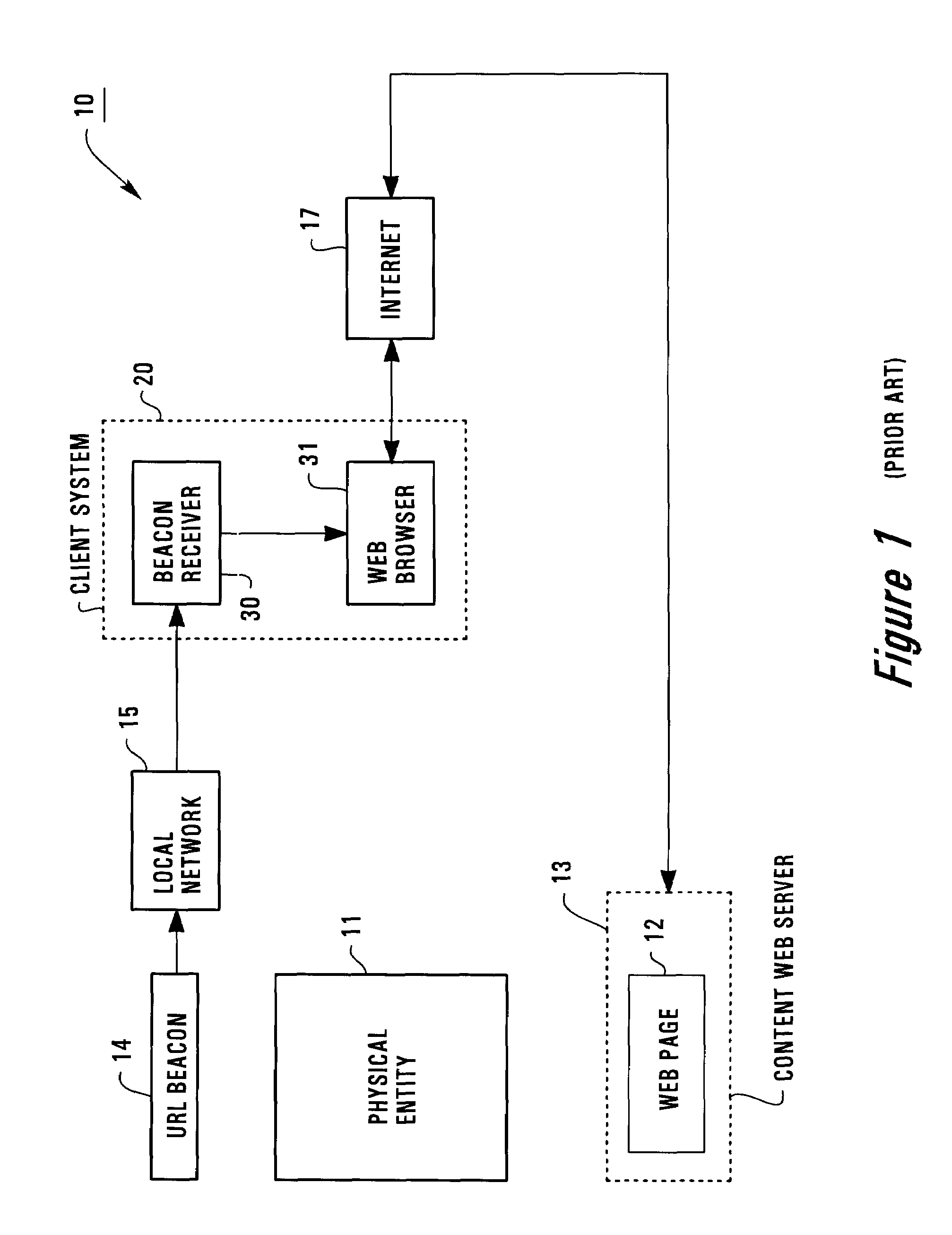
In other words, this prior art structure does not provide means for linking people who are interested in a physical entity to its web representation.
This causes difficulty and inconvenience for the users to access those web pages.
The inconvenience has increasingly become obvious because the Web has now grown to contain millions of millions of web sites and / or web pages.
This problem is also amplified by the fact that more and more people can access the Web through their mobile devices.
However, disadvantages are still associated with such prior arrangement.
One disadvantage is that the URL beacon is a physical thing that must be physically placed adjacent the physical entity or location.
In addition, the physical beacon typically has a very limited transmission range.

Method used


Image

  • Creating a virtual link between a physical location and its web representation
  • Creating a virtual link between a physical location and its web representation
  • Creating a virtual link between a physical location and its web representation

Examples


Embodiment Construction

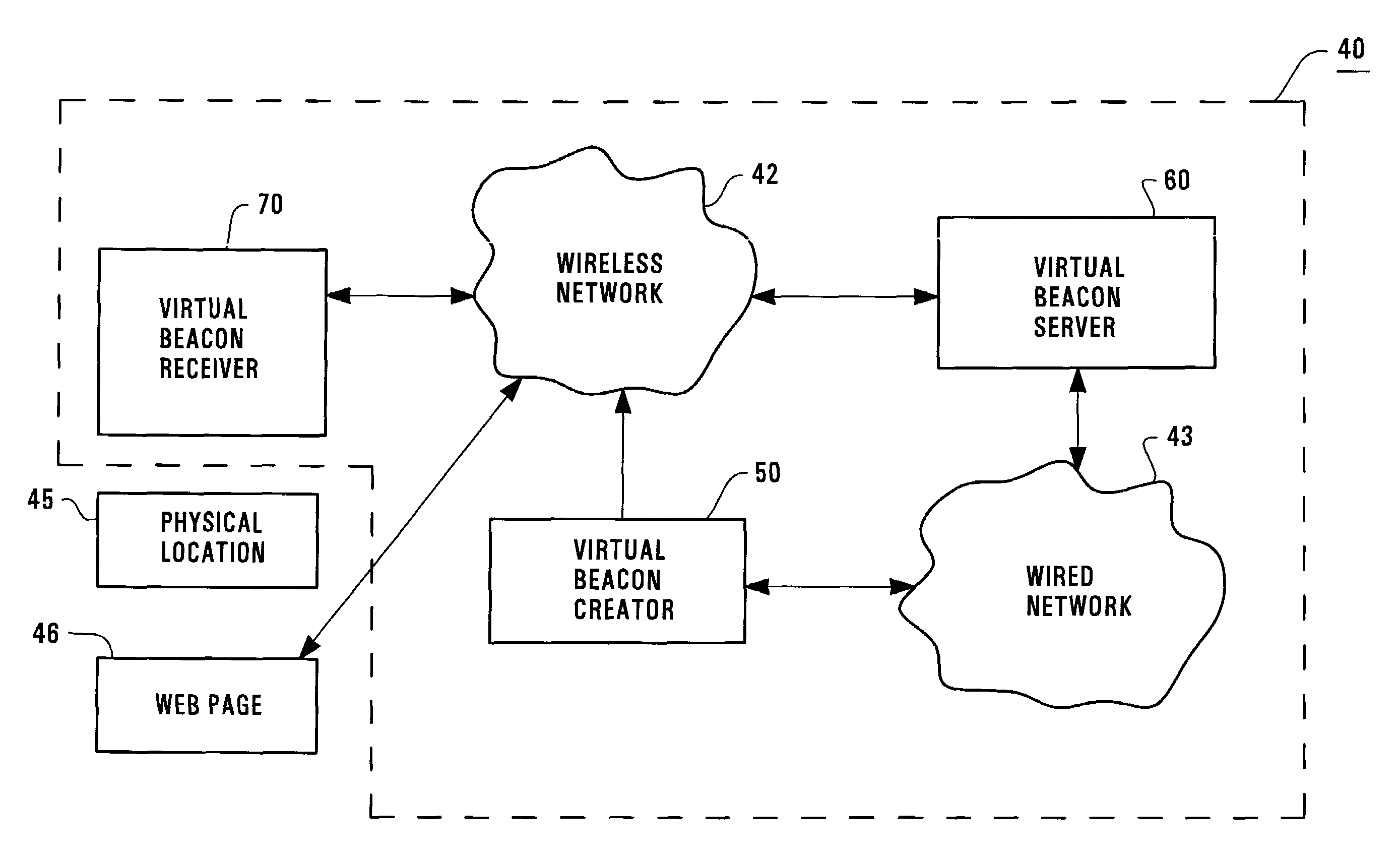
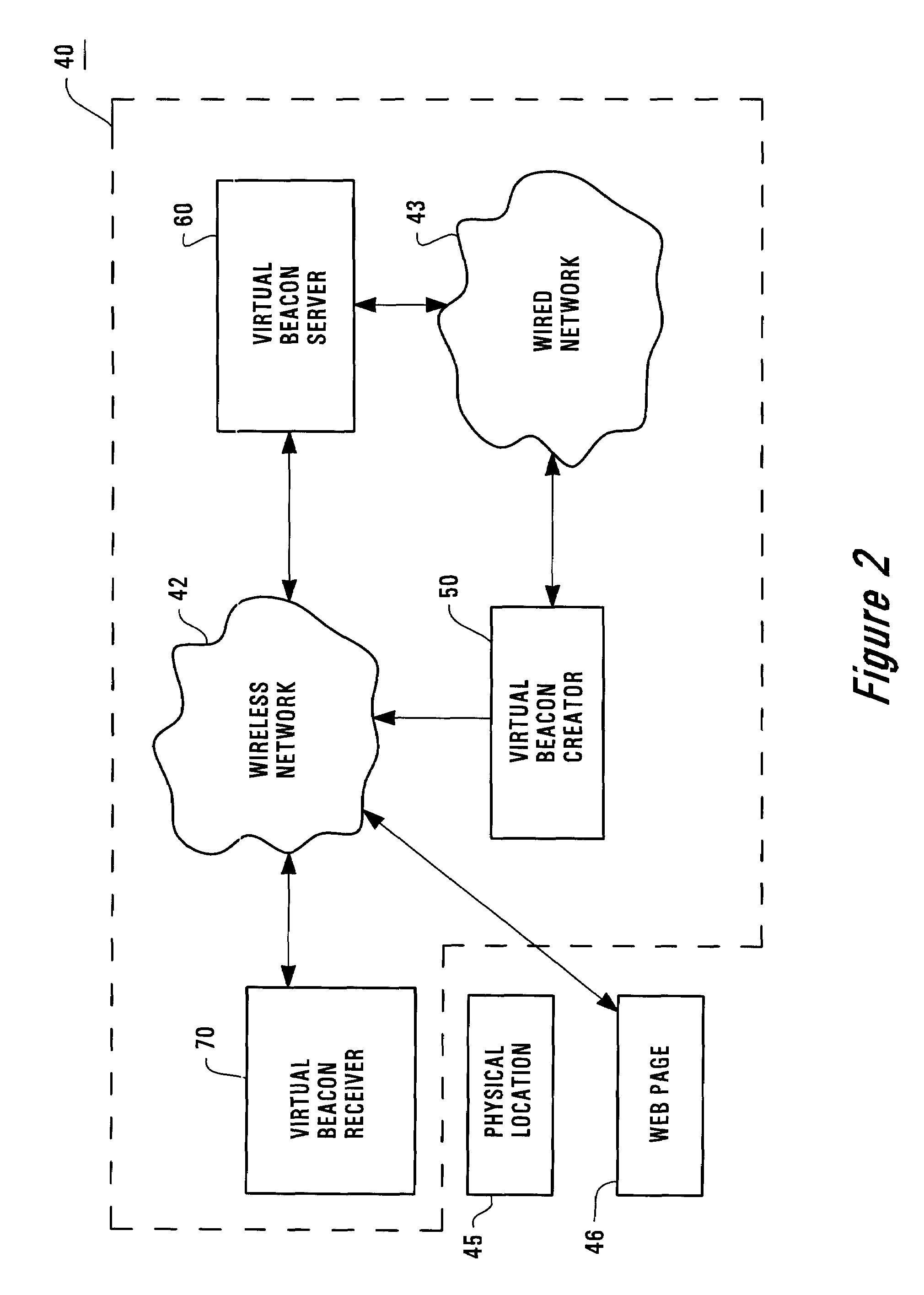
[0027]FIG. 2 shows a web navigation system 40 that implements one embodiment of the present invention. The web navigation system 40 includes a virtual beacon creator 50, a virtual beacon server 60, and a virtual beacon receiver 70. A wireless network 42 is used for communications among the above mentioned systems 50, 60, and 70. In addition, a wired network is used for communication between the virtual beacon creator 50 and the virtual beacon server 60.

[0028]The virtual beacon creator 50 can also be referred to as a virtual link creator. The virtual beacon server can also be referred to as a virtual link server. In addition, the virtual beacon receiver 70 can be referred to as a virtual link receiver or a receiver.

[0029]FIG. 2 also shows a physical location 45 and a web page 46 hosted in a content web server (not shown). The web page 46 can be accessed via the wireless network 42 by the virtual beacon receiver 70. This means that the virtual beacon receiver 70 has Internet access ca...


PUM


Abstract

A web navigation system includes a virtual link creator that creates an electronic file that contains positional data of a physical location and a web address of a web page associated with the physical location. A virtual link server system receives the electronic file. The server system can transmit the electronic file to any remote receiver system that is near the physical location via a communication network. A receiver system, capable of communicating with the server system and accessing external Internet, receives the electronic file from the server system when the receiver system is near the physical location such that the web address of the web page is virtually posted at the physical location without employing a physical object to host the web address at the physical location. A system for creating such a virtual link is also described. Also described is a system for virtually posting a web address of a web page associated with a physical location.

Description

BACKGROUND OF THE INVENTION[0001]1. Field of the Invention[0002]The present invention pertains to Internet and World Wide Web (“WWW”). More particularly, this invention relates to creating a virtual link between a three-dimensional (“3-D”) physical location (or entity) and its web representation for fast and convenient web navigation without employing any physical object to host the link at the physical location.[0003]2. Description of the Related Art[0004]As is known, the world we live in is a physical world that is formed by physical entities such as people, places, and things (or objects). For example, a bookstore is a place. So is a tourist attraction, a museum, an exhibition hall, a conference room, or a home. A book in a bookstore, a painting in a museum is a thing. Likewise, a TV in a house is a thing. A bus stop can be referred to as a place.[0005]With rapid growth of the Internet and widespread use of the Web (i.e., WWW), more and more physical entities (e.g., restaurants, ...

Claims


Application Information

Patent Timeline
IPC IPC(8): G06F15/16G06F13/00G01C21/00G06F17/30G08G1/00
CPCG06F17/30861G06F16/95
Inventor PRADHAN, SALILMORGAN, JEFFREY ASMITH, MARK T
Owner KNAPP INVESTMENT
Learn More