Bearing balls escape and wear annunciator arrangement for ball screw

a technology of bearing balls and annunciators, which is applied in the direction of gearing details, gearing, instruments, etc., can solve the problems of failure of the primary load system, and failure of the principal load system

Active Publication Date: 2007-11-27
PENDICOM LLC
View PDF4 Cites 25 Cited by
  • Summary
  • Abstract
  • Description
  • Claims
  • Application Information

AI Technical Summary

Problems solved by technology

However, in applications where a failure of a primary drive system might yielded disastrous results, a secondary drive system can be configured to assume the load.
It is a problem with such known arrangements that there is no indication provided to the operator that the primary load system has failed.
Although rare, a principal mode of failure of the principal drive system is the escape of the recirculating balls.
Additionally, there is the possibility that the balls within the system do not escape, but become worn to the point that the primary load system can be deemed to have failed.

Method used


Image

  • Bearing balls escape and wear annunciator arrangement for ball screw
  • Bearing balls escape and wear annunciator arrangement for ball screw
  • Bearing balls escape and wear annunciator arrangement for ball screw

Examples


Embodiment Construction

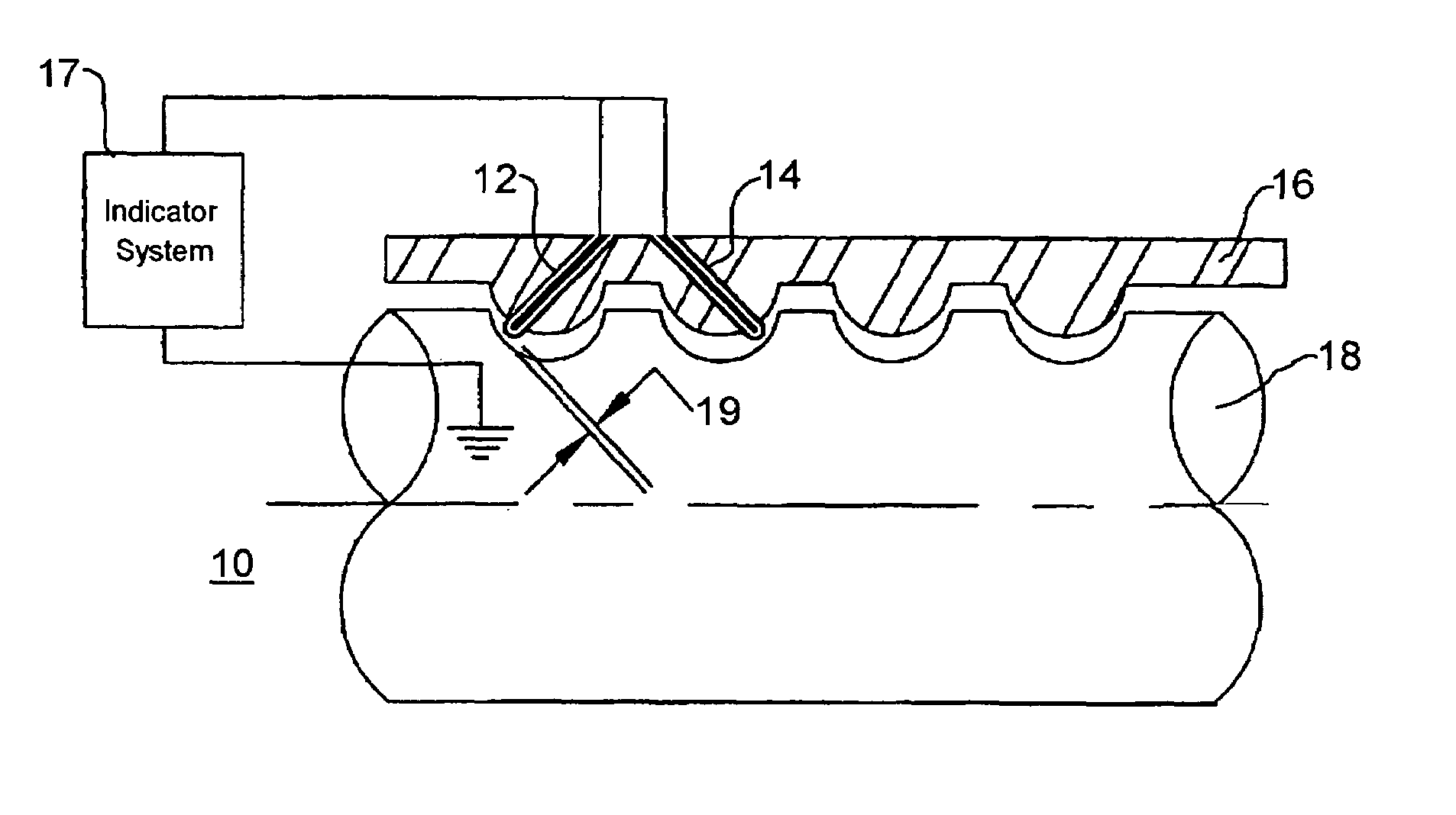
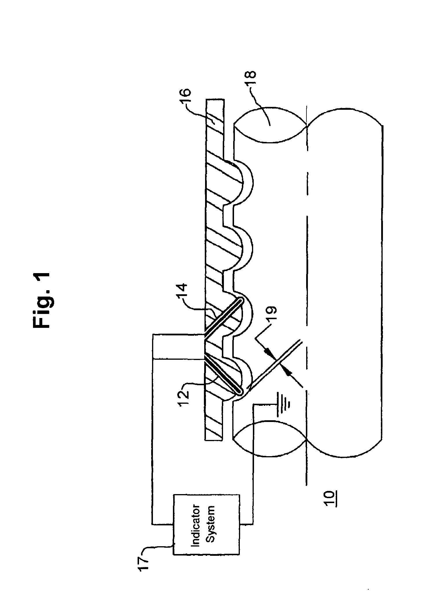
[0048]FIG. 1 is a simplified schematic representation of a screw shaft impending failure detector 10, that employs a continuity methodology of operation. The representation is shown partly in schematic mechanical representation, and partly as electrical function block, as will be described in detail below. The embodiments herein described are useful to detect wear of the mechanical components, specifically including the bearing balls (not shown in this figure), as well as the escape of the bearing balls, as would be the case in the event of a catastrophic failure. A pair of conductive cores (not specifically designated in this figure) are each encased in a respective electrically insulating material (not specifically designated in this figure) to form a pair of electrical sensors 12 and 14. In this embodiment, electrical sensors 12 and 14 are installed on a load path 16 that is shown to be threadedly engaged with a screw shaft 18.

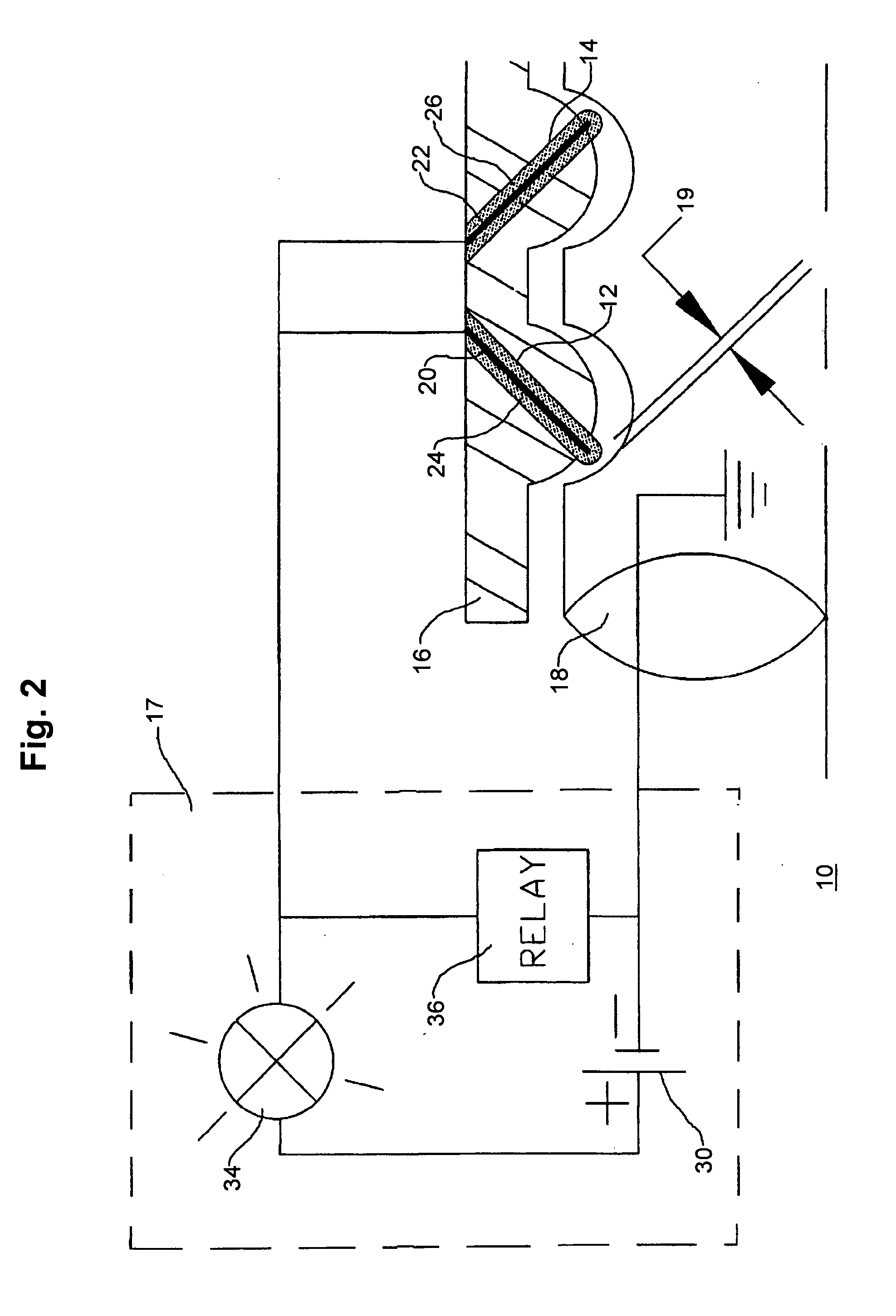
[0049]Electrical sensors 12 and 14 are shown to be co...


PUM

PropertyMeasurementUnit
axial displacementaaaaaaaaaa
electrical characteristicaaaaaaaaaa
displacementaaaaaaaaaa

Abstract

An arrangement for detecting a load bearing failure includes a primary load-carrying system for bearing axially translatably a coaxial load, said primary load-carrying system having a rotor portion and an axially displaceable stator portion. A plurality of bearing balls is interposed between the rotor and axially displaceable stator portions. A detector, which may include any of a laser measuring, an ultrasonic measuring, or a linear variable transformer or electrical contact detects wear or actual or impending failure of the primary load-carrying system. A secondary load-carrying system may be provided for bearing the coaxial load upon the event of a failure of the primary load-carrying system. The primary load-carrying system is a recirculating ball screw arrangement wherein the plurality of bearing balls is disposed in part in respective helical grooves of the rotor and axially displaceable stator portions. Wear or escape of the bearing balls is detected.

Description

RELATIONSHIP TO OTHER APPLICATION[0001]This application claims the benefit of the filing date of provisional Patent Application Ser. No. 60 / 612,997, filed Sep. 24, 2004. The disclosure of that provisional patent application is incorporated herein by reference.BACKGROUND OF THE INVENTION[0002]1. Field of the Invention[0003]This invention relates generally to ball screw drive arrangements, and more particularly, to an arrangement that provides an indication of failure resulting from the escape of the balls or the diminution in the size of the balls as a result of excessive wear.[0004]2. Description of the Related Art[0005]Primary load path failure is the type of malfunction most desired to be detected in flight controls today. Due to the vital role of ball screws in the safety of a flight, the monitoring of the integrity of the primary load path and the early and accurate detection of failures have became a requirement in modern aircraft.[0006]It is an advantageous characteristic of b...

Claims


Application Information

Patent Timeline
Patent Type & Authority Patents(United States)
IPC IPC(8): G01N3/32
CPCG01N3/56F16H25/2204F16H57/01
Inventor BALASU, MIRCEA G.MONSANTO, RAPHAEL A.
Owner PENDICOM LLC
Why Eureka
Try Eureka