Motorized pulley

a technology of motorized pulleys and pulleys, which is applied in the direction of heat exchange apparatuses, conveyers, packaging, etc., can solve the problems of reducing the life expectancy of the belt, affecting the performance and reliability of the motorized pulley, and increasing the likelihood of belt damage, so as to facilitate the operation of the brak

Active Publication Date: 2007-11-27
DODGE ACQUISITION CO +1
View PDF20 Cites 37 Cited by
  • Summary
  • Abstract
  • Description
  • Claims
  • Application Information

AI Technical Summary

Benefits of technology

[0008]In accordance with another embodiment, the present technique provides another exemplary motorized pulley. This exemplary pulley includes a housing and, also, includes an electric motor and gear assembly that are disposed in the housing. The electric motor further includes a rotatable element that is secured to the rotor and that extends beyond the housing. Accordingly, the rotatable element extends into the external environment surrounding the motorized pulley. Thus, rotation of the rotatable element may be harnessed to operate a machine element coupled thereto. For instance, the rotatable element may be coupled to a tachometer or may facilitate operation of a brake for the electric motor or a cooling fan, for instance.
[0009]In accordance with another embodiment, the present technique provides an exemplary method for manufacture of a motorized pulley. The exemplary method includes that act of disposing a gear assembly and an electric motor within the hollow interior portion of the housing. The electric motor is disposed in the housing such that a fastener receiving portion of the end cap of the electric motor at least partially defines an external surface of the motorized pulley. Advantageously, these fastener receiving surfaces facilitate thermal coupling of the electric motor to a support structure, to dissipate heat generated during operation, for instance.

Problems solved by technology

During operation, however, the internally located motor and gear assembly generate heat, which can negatively impact the performance and reliability of the motorized pulley.
Moreover, generated heat can increase the surface temperature of the pulley, thereby increasing the likelihood of damage to the belt and decreasing the life expectancy of the belt, for instance.
Unfortunately, traditional motorized pulleys isolate the motor and motor assembly from the external environment, thereby reducing the efficacy of cooling.
For instance, traditional motorized pulleys generally do not provide a thermally conductive pathway for effective and controlled dissipation of heat generated during operation.
Moreover, traditional motorized pulleys, because of this isolated nature of the motor, do not facilitate use of the torque generated by the motor.

Method used


Image

  • Motorized pulley
  • Motorized pulley
  • Motorized pulley

Examples


Embodiment Construction

[0016]As a preliminary matter, the definition of the term “or” for the purpose of the following discussion and the appended claims is intended to be an inclusive “or.” That is, the term “or” is not intended to differentiate between two mutually exclusive alternatives. Rather, the term “or” when employed as a conjunction between two elements is defined as including one element by itself, the other element itself, and combinations and permutations of the elements. For example, a discussion or recitation employing the terminology “A” or “B” includes: “A”, by itself “B” by itself and any combination thereof, such as “AB” and / or “BA.”

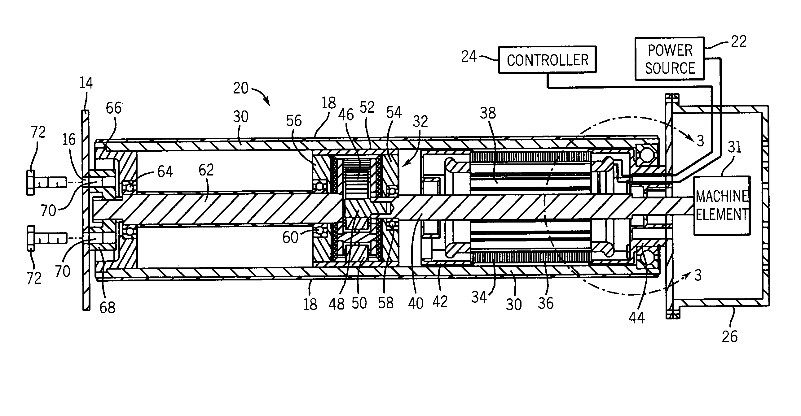
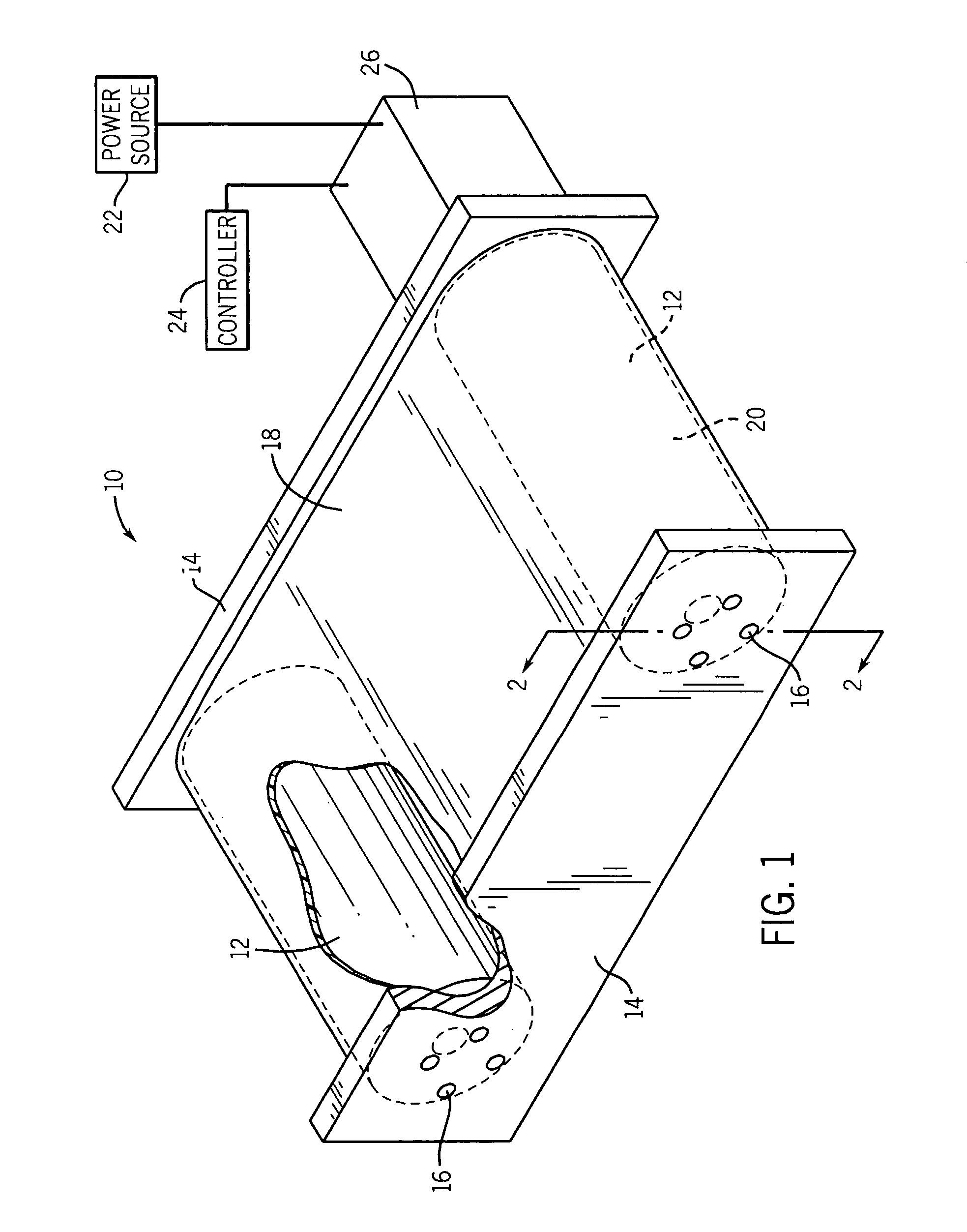
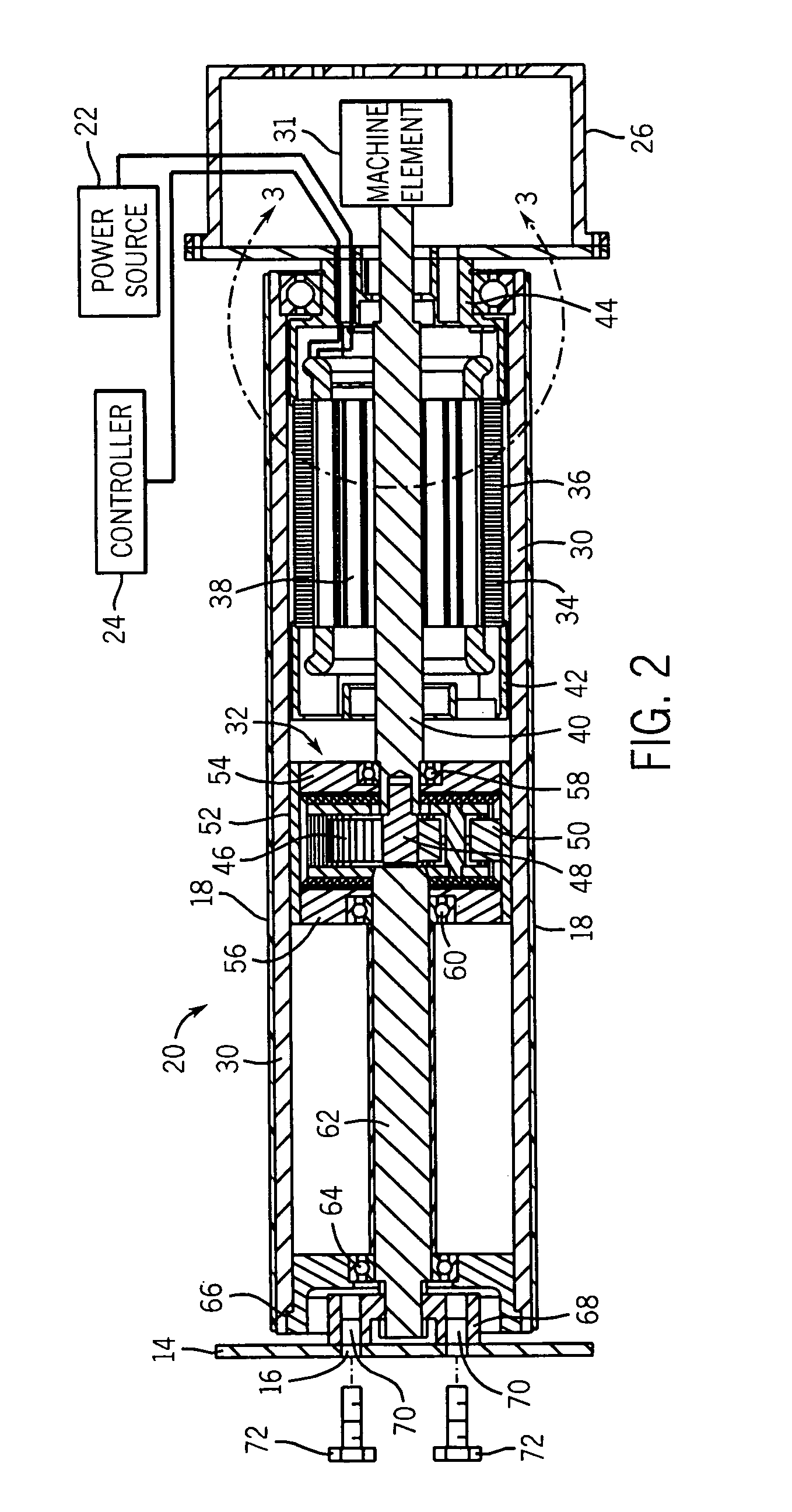
[0017]The present technique is generally directed to motorized pulleys and conveyor systems. These pulleys and conveyor systems are used in many applications, and embodiments of these items and systems are discussed further below. However, it is worth noting that the following discussion relates to exemplary embodiments of the present technique, and the appe...


PUM


Abstract

The present technique, in accordance with one exemplary embodiment, relates to a motorized pulley. The exemplary motorized pulley includes a rim or housing inside of which are disposed an electric motor and a gear assembly, which is configured to transfer torque of the electric motor to the housing. Thus, during operation of the motor, the exemplary pulley rotates the housing in relation to a support structure to which the motorized pulley is mounted. To improve the dissipation of heat generated during operation of the motor, the motor is thermally coupled to the frame. Additionally, the rotor shaft of the exemplary motorized pulley extends into the external environment surrounding the pulley, thereby facilitating the operation of a machine element located externally with respect to the pulley via the electric motor disposed within the pulley.

Description

BACKGROUND[0001]The present invention relates generally to rotating devices and, more particularly, to motorized pulleys.[0002]In many industrial settings, conveyor systems are employed to transport items from one location to another. By way of example, conveyor systems can be relatively large systems, such as those found in airport baggage areas, to relatively small systems, such as those found in commercial retail centers. In any event, traditional conveyor systems generally include a pulley that rotates with respect to a frame and that drives a belt surrounding the pulley. Indeed, traditional conveyor systems generally include a motor that drives a gear reducer, which, in turn, drives one or more pulleys that, in turn, drives movement of the belt coupled to the pulleys.[0003]To conserve space, many conveyor systems include one or more pulleys that carry a motor and a gear reducer within the interior of the pulley. Such pulleys are often referred to as motorized pulleys. Tradition...

Claims


Application Information

Patent Timeline
Patent Type & Authority Patents(United States)
IPC IPC(8): B65G13/06
CPCB65G23/08B65G2207/22
Inventor EL-IBIARY, YEHIA M.
Owner DODGE ACQUISITION CO
Why Eureka
Try Eureka