Elbow fitting with step feature for pneumatic transport system

Active Publication Date: 2007-11-27
PELLETRON CORP
View PDF17 Cites 49 Cited by
  • Summary
  • Abstract
  • Description
  • Claims
  • Application Information

AI Technical Summary

Benefits of technology

[0032]It is still another advantage of this invention that the reduction in resistance results in lower energy requirement for imposing a change in direction for the flow of product through a pneumatic transport system.
[0033]It is still another feature of this invention that the expanded shape for the outer side of the elbow fitting utilizes gravity and Bernoulli's Law to reduce the velocity of the accumulated product layer.
[0034]It is yet a further feature of this invention to provide an elbow fitting configuration that can be utilized to create either a 90 degree directional change or a 45 degree direction change for the product stream.
[0035]It is yet another advantage of this invention that the step feature of the elbow fitting creates an effective clean-out of the elbow fitting after the incoming product flow has ceased.
[0036]It is yet another object of this invention to provide an elbow fitting for pneumatic product conveying systems that is durable in construction, inexpensive of manufacture, carefree of maintenance, facile

Problems solved by technology

High air velocity and low product particle population is accomplished with low pressure resistance, but greatly increased damage to the product particles being conveyed.
Damage occurs in straight pipe sections, but is greatly increased whenever directional changes are imposed on the conveying system.
Whether the conveying system is operating under dilute phase or dense phase, the product particles suffer considerable damage during transport, particularly when changes in direction are being used.
Nevertheless, the combination of high velocity and centrifugal force does most of the damage, particularly on heat sensitive plastic compounds.
Elbow fittings used in pneumatic conveying systems typically suffer wear at the elbow curve in line with the product flow into the elbow fitting, whether the elbow fitting is a short radius elbow or a long radius sweep elbow fitting.
The bouncing product particles crea

Method used


Image

  • Elbow fitting with step feature for pneumatic transport system
  • Elbow fitting with step feature for pneumatic transport system
  • Elbow fitting with step feature for pneumatic transport system

Examples


Embodiment Construction

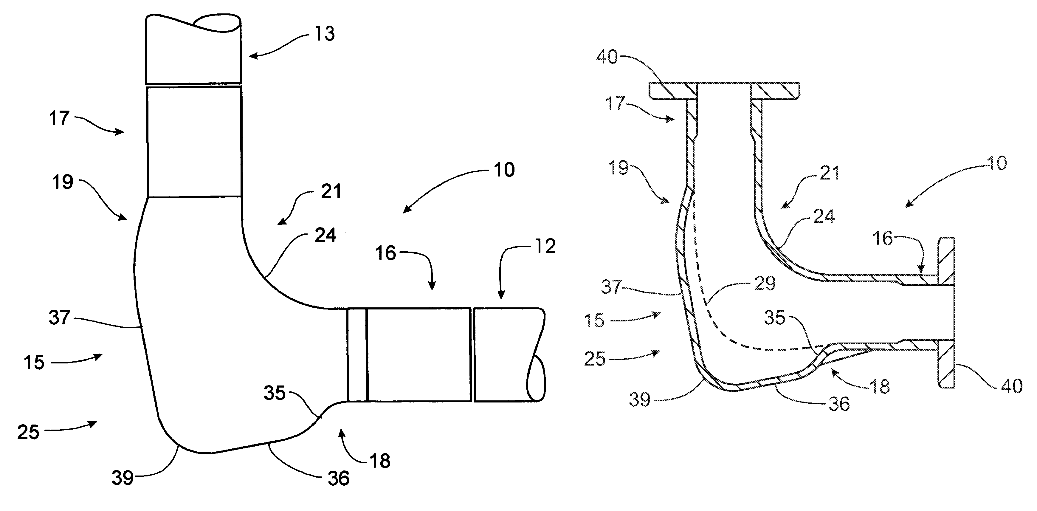
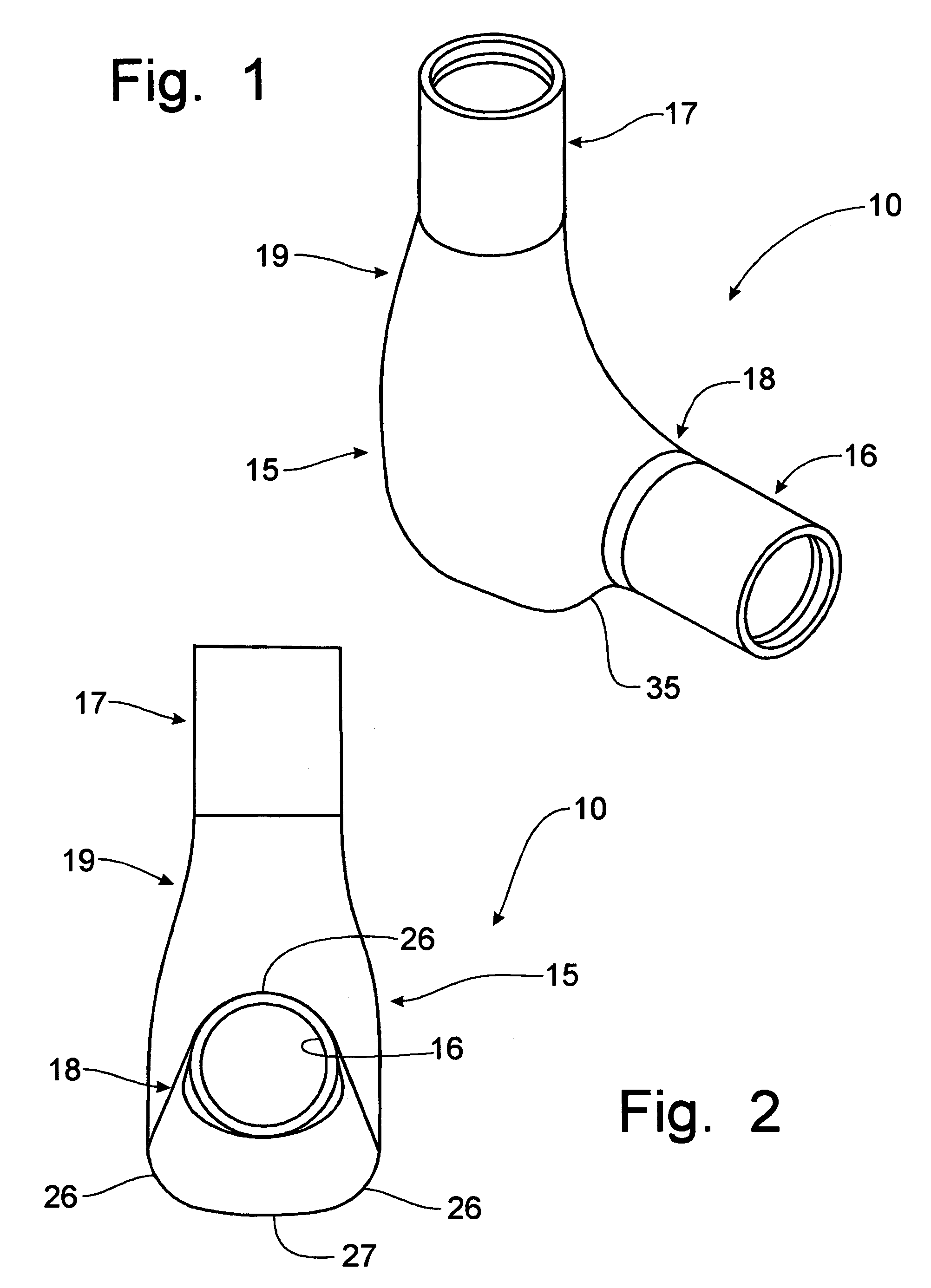
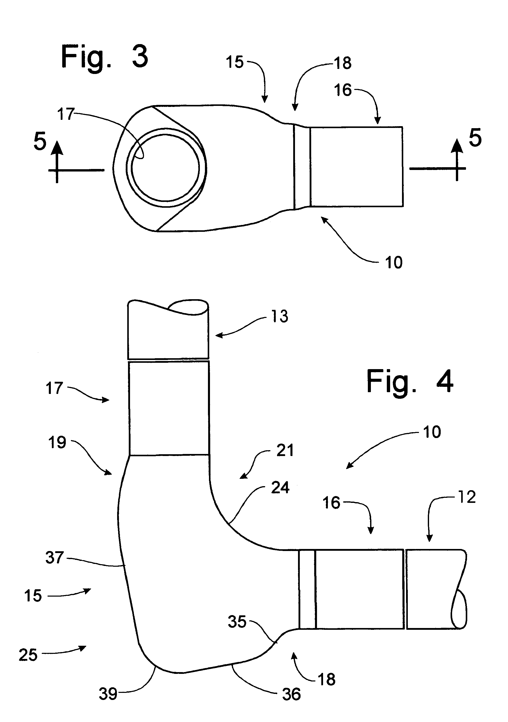
[0047]Referring now to FIGS. 1-5, a 90 degree elbow fitting for use in a pneumatic product conveying system, and incorporating the principles of the instant invention, can best be seen. The elbow fitting 10 is to be connected to a conventional inlet pipe 12 and an outlet pipe 13 to provide a directional change for the path of travel of the product within the pipes 12, 13. While the instant invention is intended for use with dilute phase pneumatic systems, an elbow fitting 10 incorporating the principles of the instant invention can also be utilized with dense phase pneumatic systems. Typically, dense phase pneumatic systems fill the pipe with product particles and inject a sufficient amount of air to effect movement of the product through the pipe 12, 13. Accordingly, a substantial amount of product particles are being moved at a significant velocity through the pipes 12, 13. Changing directions typically results in wear from the product particles rubbing against the inside of the f...


PUM


Abstract

An elbow fitting is used in a pneumatic product conveying system in which the fitting expands from the inlet pipe along the outer side of the elbow fitting to enable a layer of accumulated product particles to be formed so as to move at a lower velocity than the velocity of the incoming product stream while establishing a moving contact surface for deflecting incoming product particles toward the outlet pipe with a minimum of pressure resistance and product attrition. The accumulated product particles are discharged from the elbow fitting by incorporating a step in the outer surface of the elbow fitting to create a Bernoulli effect causing the accumulated product particles to enter the air flow after the incoming flow of product particles has ceased. The particles in the accumulated layer are replenished from the incoming flow during operation of the elbow fitting.

Description

CROSS-REFERENCE TO RELATED APPLICATIONS[0001]This application is a continuation-in-part of U.S. patent application Ser. No. 10 / 743,117, filed on Dec. 22, 2003, now U.S. Pat. No. 6,951,354. This application also claims domestic priority on U.S. Provisional Patent Application Ser. No. 60 / 567,954, filed May 4, 2004.BACKGROUND OF THE INVENTION[0002]The present invention relates generally to pneumatic transport systems and, more particularly, to a fitting for pneumatic pipes to permit a change in direction of the material being conveyed therein.[0003]Conveying solid particles injected into a high velocity stream of air contained within a pipe or tube is well known in industry. Dilute phase velocities often exceed sixty miles per hour and use up to one pound of air to move as much as five pounds of product per minute through the pipe. Typical air pressures for dilute phase systems will range from eight to twelve psig. High air velocity and low product particle population is accomplished w...

Claims


Application Information

Patent Timeline
IPC IPC(8): F16L43/00
CPCF16L43/001B65G53/523
Inventor PAULSON, JEROME I.
Owner PELLETRON CORP
Why Eureka
Try Eureka