
Electrical connector

a technology of electrical connectors and connectors, applied in the direction of electrical discharge lamps, coupling device connections, instruments, etc., can solve the problems of unfavorable shape and high manufacturing cost, and achieve the effect of simple manufacturing process and enhanced arrangement density

Inactive Publication Date: 2007-11-27
LOTES
View PDF6 Cites 21 Cited by
  • Summary
  • Abstract
  • Description
  • Claims
  • Application Information

AI Technical Summary

Benefits of technology

The present invention provides an electrical connector that is easy to make, low-cost, and suitable for dense arrangement. The connector has an insulating body with receiving holes containing first and second terminals that are inclinedly arranged. The second terminal is a flat shape, which makes it simple to manufacture by stamping. The arrangement density of the first and second terminals is enhanced by the inclined arrangement.

Problems solved by technology

However, the sizes of the metal shell and the probe in the aforementioned invention are small, resulted in a high manufacturing cost.
On the other hand, if the probe is a flat shape, its manufacture may be easier but the shape is unfavorable to the high arrangement density in the insulating body.

Method used


Image

  • Electrical connector
  • Electrical connector
  • Electrical connector

Examples


Embodiment Construction

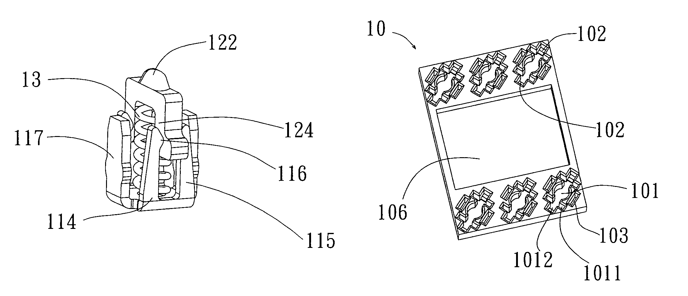
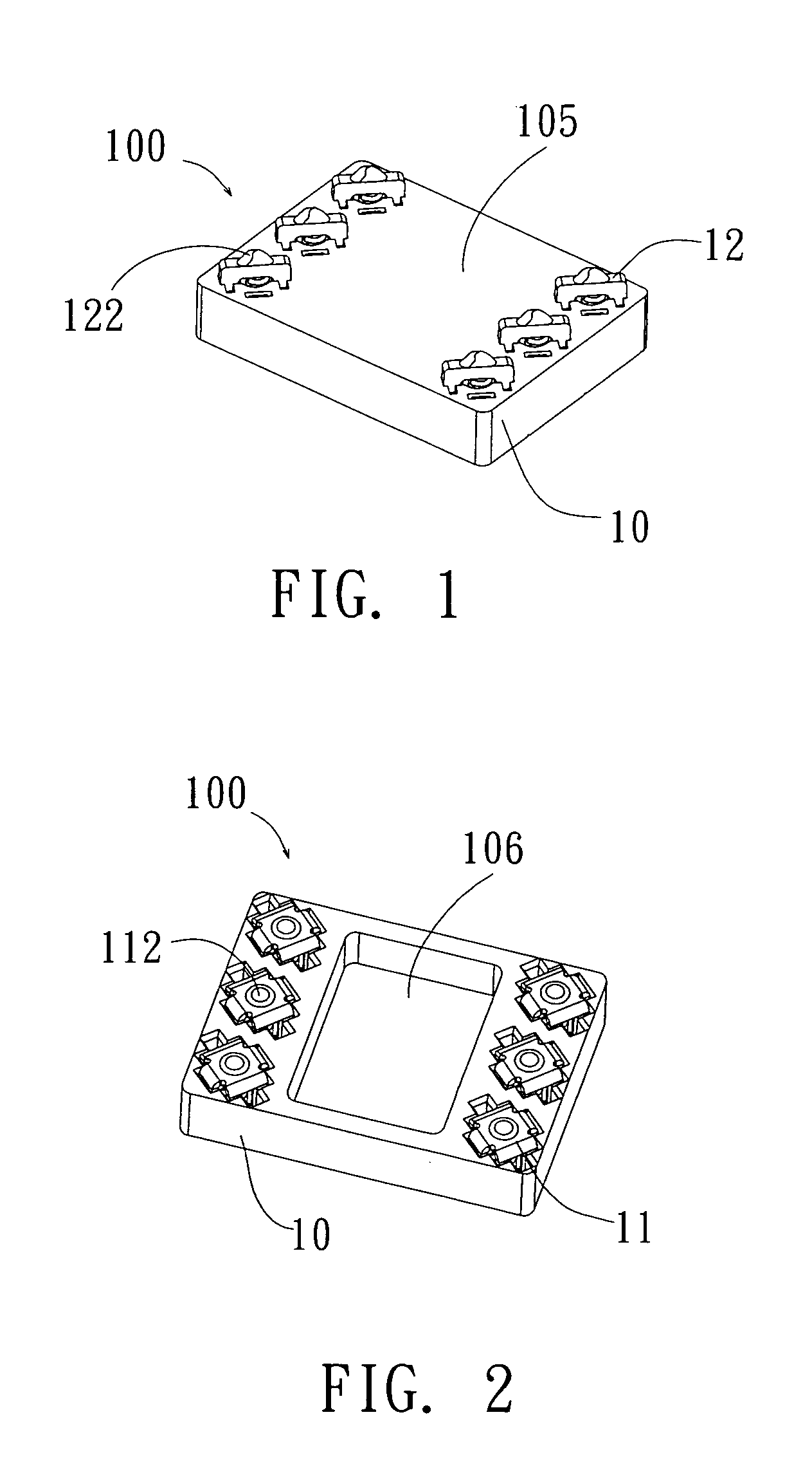
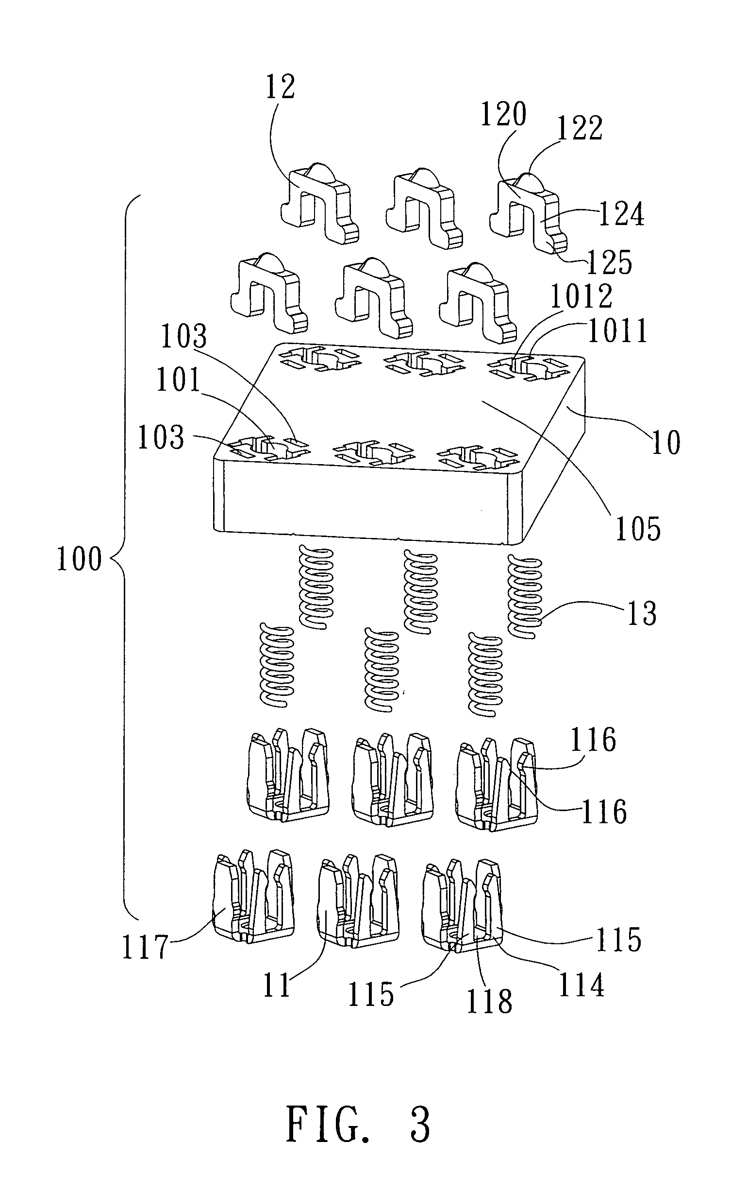
[0014]Referring to FIGS. 1 to 6, an electrical connector 100 according to the present invention may be connected with external two electronic devices (not shown), comprising an insulating body 10, at least a first terminal 11, at least a second terminal 12, and an elastic body 13 disposed between the first terminal 11 and the second terminal 13 (in the present embodiment, the elastic body 13 is, for example but not limited to, a spring; of course, it may be other material with similar property, a polymer block (not shown), for example).

[0015]The insulating body 10 is inclinedly disposed with two rows of terminal receiving holes 101 penetrating from its upper to lower surfaces. The terminal receiving hole 101 comprises the first terminal receiving hole 1011 for receiving the first terminal 10 and the second terminal receiving hole 1012 which is perpendicular to and inter-penetrating with the first terminal receiving hole 1011. The first terminal receiving hole 1011 has a stop wall 10...


PUM


Abstract

The present invention discloses an electrical connector, comprising an insulating body disposed with a plurality of receiving holes, each of which is disposed with a first terminal and a second terminal inter-penetrating each other, wherein the second terminal is a flat shape and the first and second terminals are inclinedly arranged in the terminal receiving hole; and an elastic body disposed between the first and second terminals. The second terminal of the electrical connector is a flat shape so that it may be manufactured by stamping, which is a simple manufacturing process; the first and second terminals are inclinedly arranged in the terminal receiving hole of the insulating body, which can enhance the arrangement density.

Description

FIELD OF THE INVENTION[0001]The present electrical connector relates to an electrical connector with pressing contacts.BACKGROUND OF THE INVENTION[0002]Conventional electrical connector with pressing contacts, the China Patent No 02293473 for example, comprises a metal shell, a probe, and a spring, wherein the spring is disposed between the metal shell and the probe. The probe has a spherical contact portion in order to render effective contacts between the probe and the external electronic devices inserted from any direction. This design can prevent the contact from being limited in certain directions, thereby enhancing the reliability of signal transmission. However, the sizes of the metal shell and the probe in the aforementioned invention are small, resulted in a high manufacturing cost. On the other hand, if the probe is a flat shape, its manufacture may be easier but the shape is unfavorable to the high arrangement density in the insulating body.[0003]Consequently, it is neces...

Claims


Application Information

Patent Timeline
Patent Type & Authority Patents(United States)
IPC IPC(8): H01R12/00
CPCH01R12/716H01R13/2421G01R1/0466
Inventor CHEN, MING-HAO
Owner LOTES
Learn More