

Syringe/plunger coupling
a technology of syringe and plugger, which is applied in the field of injectors, can solve the problems that cannot be removed by longitudinal motion, and achieve the effect of increasing the accuracy of fluid injection
- Summary
- Abstract
- Description
- Claims
- Application Information
AI Technical Summary
Benefits of technology
Problems solved by technology
Method used
Image

Examples
Embodiment Construction
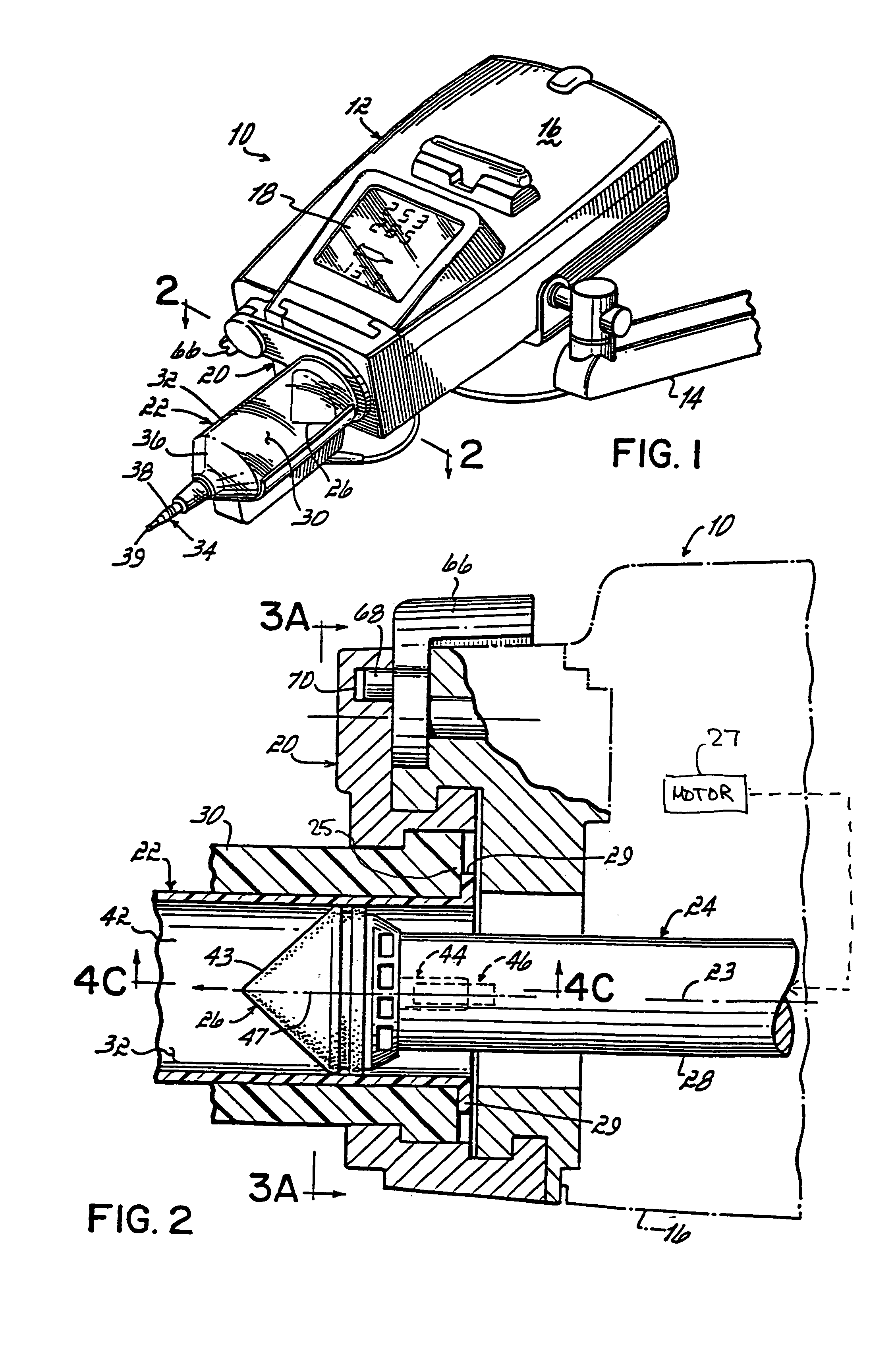
[0026]Referring to FIG. 1, the injector head 12 is depicted attached to an arm 14, which in turn may be mounted to a ceiling, wall or floor joint. This allows motion of the injector head 12 that it may be positioned to load the syringe 22 and to inject fluids into an animal subject. Surrounding the inner mechanism of the injector 10 is the injector housing 16. This housing includes a display panel 18. The display panel 18 aids the operator of the injector 10 in monitoring amounts of fluid injected into an animal subject.
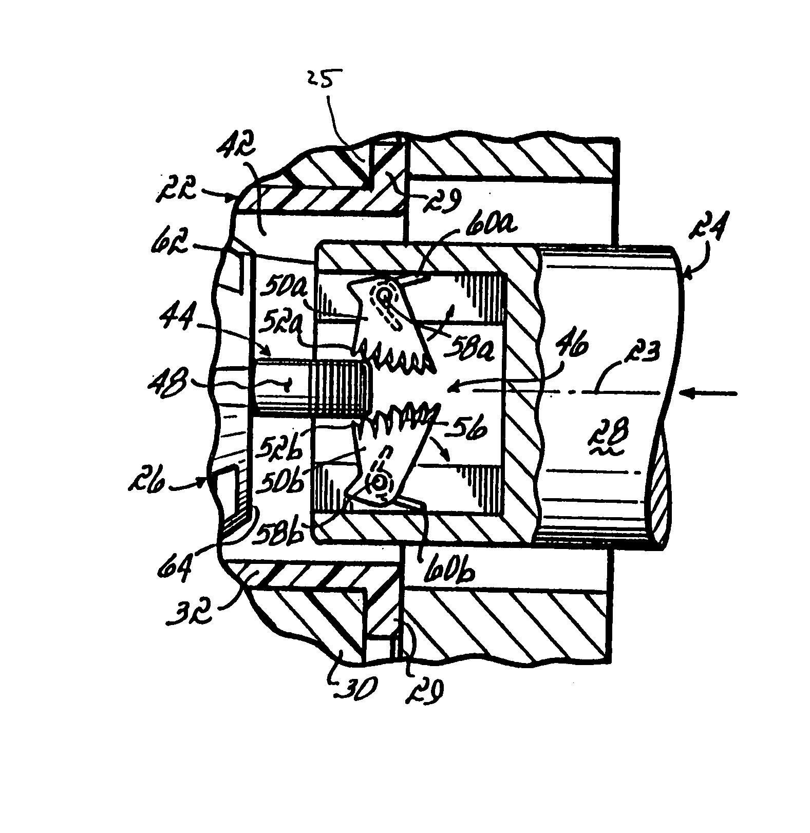
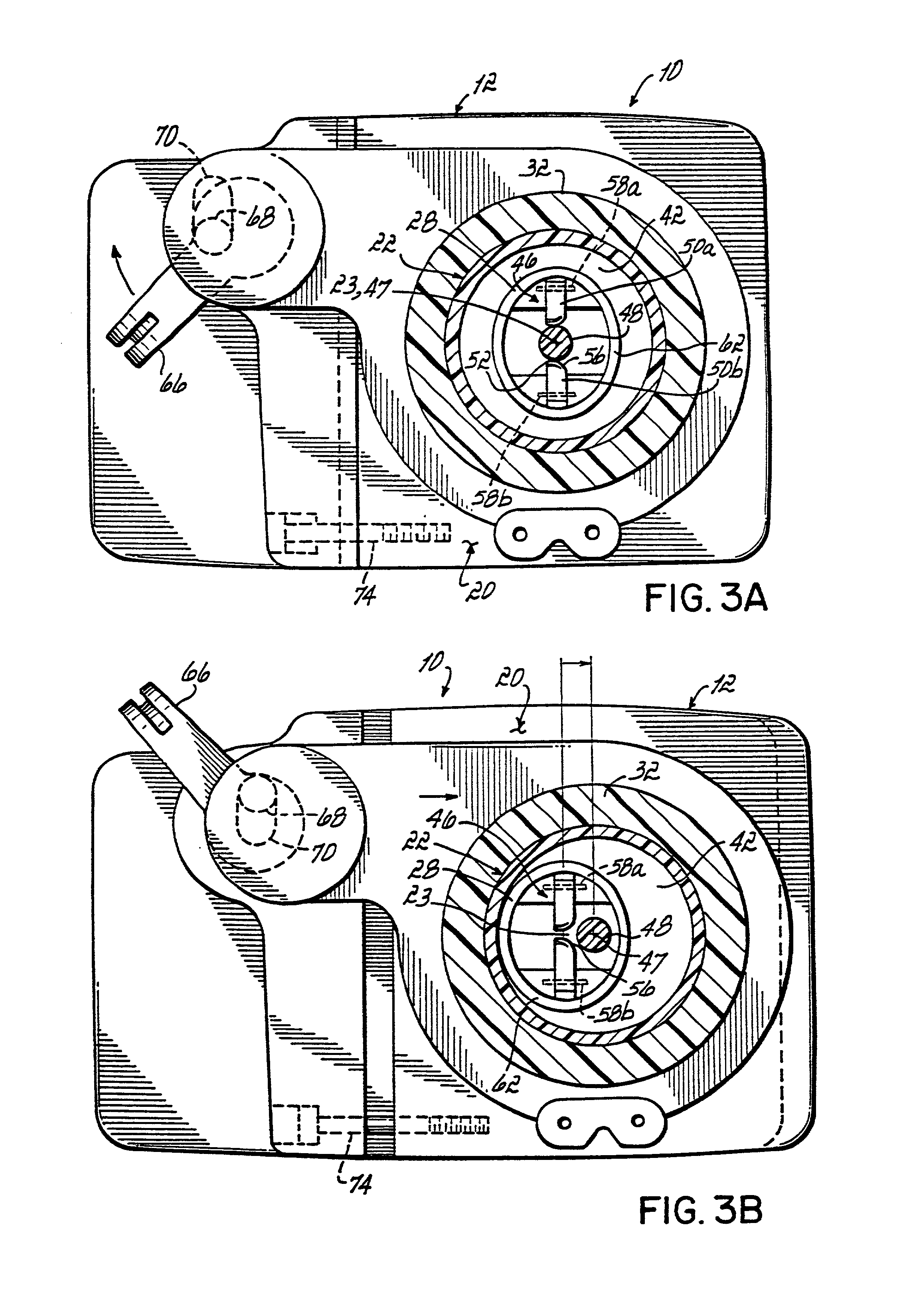
[0027]On the forward end of the injector housing 16, positioned between the injector 10 and the syringe 22, is a face plate 20. This face plate 20 is slidable along a plane perpendicular to the longitudinal axis 23 of the motion of the drive shaft 24 of the injector 10. The purpose of this face plate 20 is to facilitate connection between the injector housing 16 and the syringe 22, and to facilitate disengagement of a coupling element 44 of a syringe plunger 26 from ...
PUM
 Abstract
Description
Claims
Application Information