Diaphragm for use in switch, method for manufacturing thereof, membrane switch, and input device

a technology for diaphragms and switches, which is applied in the direction of contacts, snap-action arrangements, contact surface shapes/structures, etc., can solve the problems of not providing satisfactory “click feeling” and impairing “click feeling to users, so as to reduce the load required for making a click, reduce the area of a deformed portion, and achieve satisfactory “click feeling

Inactive Publication Date: 2007-11-27
THE FUJIKURA CABLE WORKS LTD
View PDF30 Cites 69 Cited by
  • Summary
  • Abstract
  • Description
  • Claims
  • Application Information

AI Technical Summary

Benefits of technology

[0011]The invention was conceived in light of the above-described circumstances, and a first aspect of the invention is directed to a dome-shaped diaphragm, including a convex portion; a base portion provided on an outer periphery of the convex portion; and a hole provided in at least one of the convex portion and the base portion. With the switch diaphragm according to the first aspect of the invention, the load required for making a click can be reduced by reducing the area of a deformed portion upon a click by providing the hole in the convex portion, or in the base portion, or in both the convex and the base portions of the dome-shaped diaphragm. Thus, a satisfactory “click feeling” can be obtained even with a diaphragm having a reduced size or having an extended operating stroke.
[0012]Furthermore, a second aspect of the invention is directed to a dome-shaped diaphragm, including: a convex portion; a base portion provided on an outer periphery of the convex portion; and a reduced thickness portion provided in at least one of the convex portion and the base portion. With the switch diaphragm according to the second aspect of the invention, the load required for making a click is reduced by providing a reduced thickness portion in the dome-shaped diaphragm having the convex portion and the base portion, in the convex portion, or in the base portion, or in both the convex and the base portions. Thus, a satisfactory “click feeling” can be obtained even with a diaphragm having a reduced size or having an extended operating stroke.
[0013]Furthermore, the reduced thickness portion formed in the convex portion, or in the base portion, or in both the convex and the base portions of the round dome-shaped diaphragm reduces the thickness of the deformed portion. Thus, the load required for making a click can be reduced, and a satisfactory “click feeling” can be obtained.

Problems solved by technology

However, a small-diameter diaphragm has a short operating stroke, which does not provide a satisfactory “click feeling” to users.
However, a larger load is required to click a round dome-shaped diaphragm having a large curvature, which may impair the “click feeling.”

Method used


Image

  • Diaphragm for use in switch, method for manufacturing thereof, membrane switch, and input device
  • Diaphragm for use in switch, method for manufacturing thereof, membrane switch, and input device
  • Diaphragm for use in switch, method for manufacturing thereof, membrane switch, and input device

Examples


first embodiment

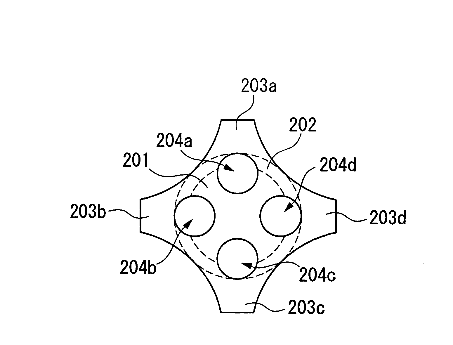
[0048]The switch diaphragm 210 of the first embodiment includes a round dome-shaped diaphragm main body having a convex curved portion 201 and a base portion 202, and leg portions 203 (203a-203d) that are formed steeper than the base portion 202 provided around the outer periphery of the diaphragm main body. The diaphragm main body and the leg portions 203 are formed in one piece in order to extend an operating stroke of the switch diaphragm. Furthermore, at least one hole 204 (204a-204d) is formed in the diaphragm 210 in order to reduce the load required for making a click. That is, the leg portions 203 are supporting members for the diaphragm that are provided around the outer periphery of the dome-shaped diaphragm main body in order to extend the operating stroke, and are formed as protrusions extending from portions of the outer periphery of the base portion 202. The switch diaphragm 210 having the leg portions 203 is placed on a wiring board with the leg portions 203 coming in ...

third embodiment

[0068]The reduced thickness portions 205 are provided extending over the convex curved portion 201 and the base portion 202 in the However, it should be noted that reduced thickness portions 205 extending over the base portion 202 and the leg portions 203 may be provided; the reduced thickness portions 205 may be provided extending over the convex curved portion 201, the base portion 202, and the leg portions 203; or reduced thickness portions 205 extending over the convex curved portion 201, or the base portion 202, or the leg portions 203 may be provided.

[0069]It should be noted that reduced thickness portions 205 formed extending over the convex curved portion 201 and the base portion 202 may be reduced thickness portions 205 formed in the boundary between the convex curved portion 201 and the base portion 202, and reduced thickness portions 205 extending the base portion 202 and the leg portions 203 may be reduced thickness portions formed in the boundary between the base porti...

fourth embodiment

[0072]The diaphragm of the fourth embodiment is a round dome-shaped switch diaphragm 310 including a convex curved portion 301 and a base portion 302.

[0073]It should be noted that the round dome-shaped switch diaphragm 310 shown in FIG. 7 is placed above a wiring board so that the periphery thereof (the base portion 301) comes in contact with a C-shaped first electrode. The base portion 301 deforms the round dome-shaped switch diaphragm 310 that comes in contact with the first electrode, thereby making the center of the switch diaphragm 310 come in contact with the second electrode. As a result, an electrical contact is defined between the first electrode and second electrode via a diaphragm that is made of a conductive material, for example, SUS steel or a copper alloy.

[0074]According to this embodiment, in order to reduce the load required for making a click of the switch, at least one hole 303 is provided in the convex curved portion 301, or in the base portion 302, or in both th...


PUM


Abstract

A dome-shaped diaphragm includes a convex portion; a base portion provided on an outer periphery of the convex portion; and a pressing force reducing portion provided in at least one of the convex portion and the base portion. Examples of the pressing force reducing portion may be a hole portion, a reduced thickness portion or any other feature that reduces the pressing force.

Description

CROSS-REFERENCE TO RELATED APPLICATIONS[0001]This application is based upon and claims the benefit of priority from Japanese Patent Application No. 2004-324374, filed Nov. 8, 2004, and Japanese Patent Application No. 2004-346886, filed Nov. 30, 2004, the contents of which are incorporated herein in their entirety by reference.BACKGROUND OF THE INVENTION[0002]1. Field of the Invention[0003]The invention relates to a diaphragm for use in a switch employing a dome-shaped switch for various electronic apparatuses, and a method for manufacturing the same. In addition, the invention relates to a membrane switch and an input device employing the above diaphragm for use in a switch.[0004]2. Description of the Related Art[0005]Dome-shaped switches are used in various electronic apparatuses. Such switches include, as shown in FIG. 1A, a contact member (hereinafter, referred to as “diaphragm”) 103 made of a conductive material and which is disposed on a wiring board 100 having a C-shaped first...

Claims


Application Information

Patent Timeline
Patent Type & Authority Patents(United States)
IPC IPC(8): H01H5/30
CPCH01H13/48
Inventor NISHIMURA, TATSUYAKASAI, TOSHIAKISAKURABA, YUUITSUMISAKI, NOBUMASA
Owner THE FUJIKURA CABLE WORKS LTD
Why Eureka
Try Eureka