Printed circuit board transformer

a transformer and printed circuit board technology, applied in the field of transformers, can solve the problems of large power circuits and large body of transformers, and achieve the effects of reducing magnetic leakage flux, high driving efficiency, and enhancing magnetic coupling

Inactive Publication Date: 2007-11-27
KEIHIN CORP
View PDF7 Cites 15 Cited by
  • Summary
  • Abstract
  • Description
  • Claims
  • Application Information

AI Technical Summary

Benefits of technology

[0009]The present invention has been made to solve the problem as mentioned above. Objects of the invention are to provide a PCB transformer, which can suppress a voltage fluctuation in each output channel to supply a stable output without the need for a larger body, even though an input load fluctuates.
[0011]According to the present invention, a magnetic coupling can be enhanced between the input coils and the output coils without the need for a larger body of the transformer, especially a larger height along a radial direction of the core. That is, a magnetic leakage flux can be reduced to obtain high driving efficiency as a power transformer. Further, even if a power load fluctuates in the input coil, low magnetic leakage flux can suppress the voltage fluctuation in each output channel to provide stable output.

Problems solved by technology

However, the body of the transformer becomes larger, as the output coils become thicker.
As a result, the power circuits become larger.

Method used


Image

  • Printed circuit board transformer
  • Printed circuit board transformer
  • Printed circuit board transformer

Examples


Embodiment Construction

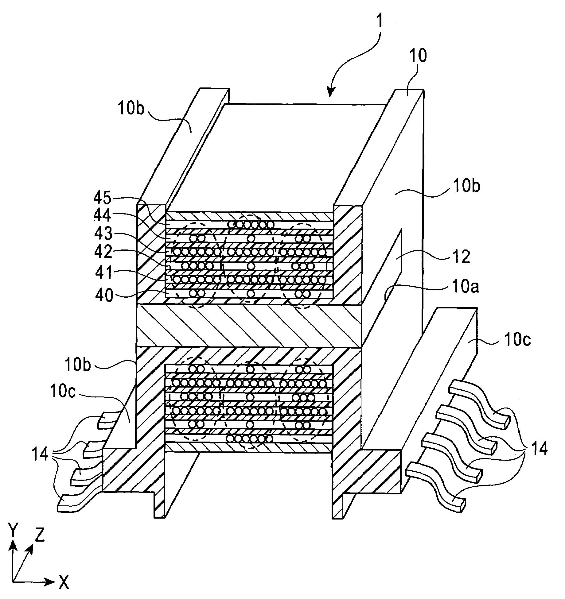
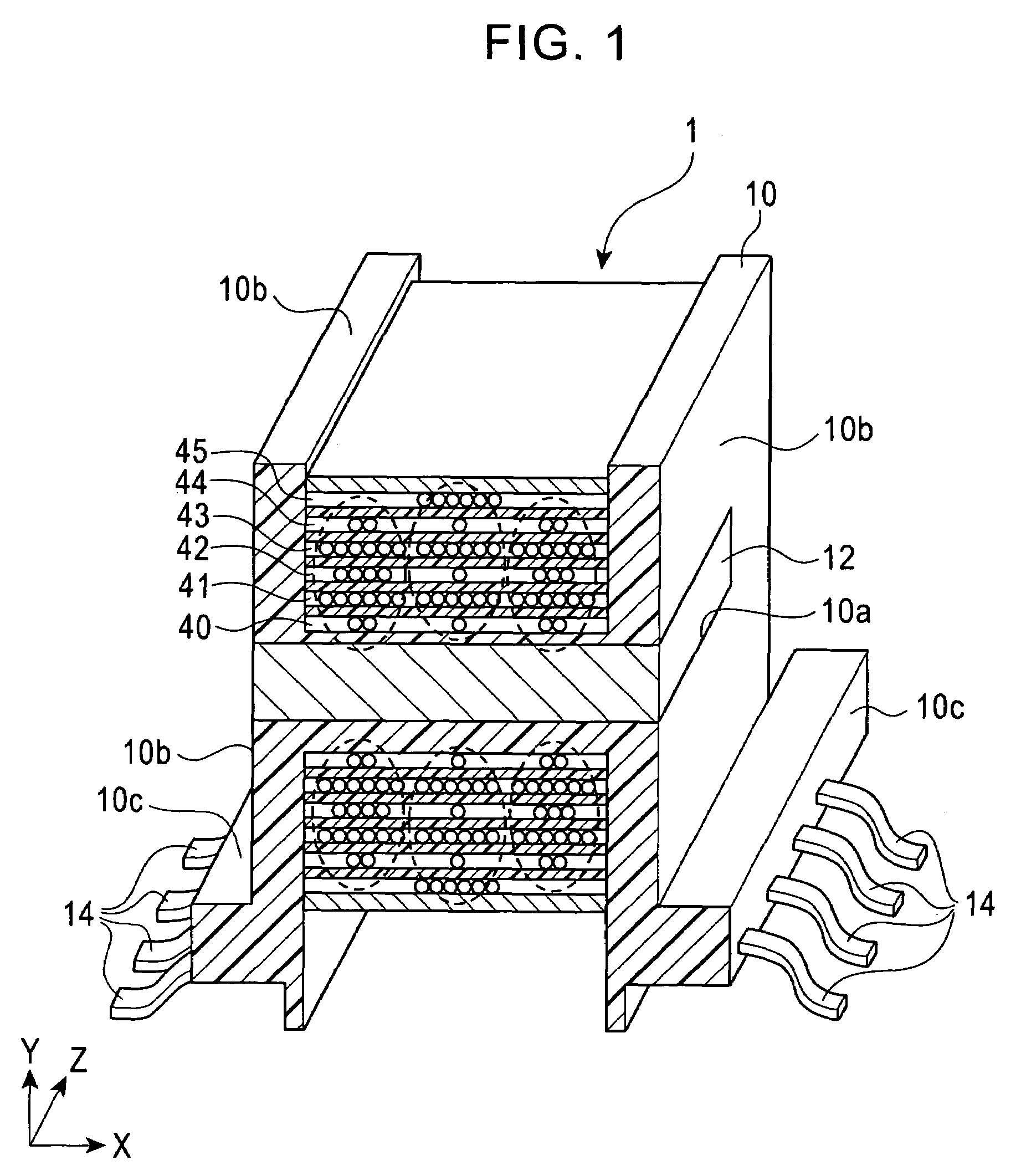
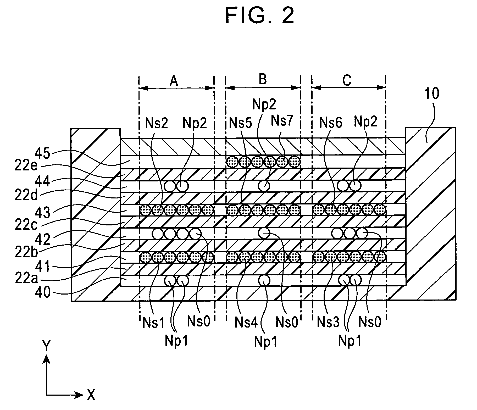
[0018]In a PCB transformer according to the present invention, an input winding for an input (primary) line is separately wound around a core as plural input coils spaced from each other along a longitudinal direction of the core. That is, these input coils are spaced from each other along the core axis by “winding in a division space”. An output winding for an output (secondary) line corresponding to one output channel is wound as an output coil with correspondence to one input coil wound by “winding with a division space”. In this coil structure, it is easy to control a magnetic field produced by the input coil, and a magnetic coupling can be enhanced between the input and output coils. Further, a magnetic leakage flux can be reduced to stabilize outputs of the transformer. The transformer can become smaller since the input coil is not divided to several layers.

[0019]Embodiments of a PCB transformer according to the present invention will be described hereinafter in detail with re...


PUM

PropertyMeasurementUnit
widthaaaaaaaaaa
densityaaaaaaaaaa
electric poweraaaaaaaaaa

Abstract

An object of the invention is to provide a PCB transformer having plural output channels, which can suppress a voltage fluctuation in each output channel to supply a stable output without the need for a larger body, even though an input load fluctuates. The PCB transformer include, a core having a core axis, a first layer including a winding for each input line separately wound around said core as plural input coils spaced from each other along the core axis, and a second layer including a winding for an output line corresponding to each output channel separately wound on said first layer as plural output coils spaced from each other along the core axis. One of the input coils and one of the output coils are disposed in one of winding regions defined along the core axis. In each the winding region, one coil having a narrower width of the input coil or the output coil is disposed within a width of another coil along said core axis.

Description

BACKGROUND OF THE INVENTION[0001]1. Field of the Invention[0002]This invention relates to a transformer for being mounted on a printed circuit board (hereinafter, it is referred as “PCB transformer”.), and particularly to a multi-channel insulated power PCB transformer having plural output channels.[0003]2. Description of the Related Art[0004]When an electronic device comprises a plurality of control circuits, each control circuit is individually supplied with its electric power from the power circuit. Such power circuit includes a multi-channel insulated power transformer which can produce a plurality of independent power from a single power source. The multi-channel insulated power transformer has, typically, coil structures comprising input (primary) coils for being supplied with the electric power from the outside of the device and output (secondary) coils, which is independent each other, for being connected to the control circuit. For the purpose of downsizing electric devices...

Claims


Application Information

Patent Timeline
Patent Type & Authority Patents(United States)
IPC IPC(8): H01F27/28
CPCH01F27/323H01F27/2823H01F2005/046H01F2005/043H01F41/062H01F41/068
Inventor SUZUKI, KOJITAKEBAYASHI, KENICHIABE, SEIICHIROCHIBA, TAKESHIKATANODA, TOMOYA
Owner KEIHIN CORP
Why Eureka
Try Eureka