Thermally compensated fiber bragg grating mount

a technology of fiber bragg grating and thermal compensation, which is applied in the direction of instruments, fluid pressure measurement, optical elements, etc., can solve the problem of less compliant grating mounts than sensor mandrels

Active Publication Date: 2007-11-27
UNITED STATES OF AMERICA
View PDF1 Cites 20 Cited by
  • Summary
  • Abstract
  • Description
  • Claims
  • Application Information

AI Technical Summary

Benefits of technology

[0011]Another object of the present invention is a FBG package that can be used in the automated construction or assembly of sensor array...

Problems solved by technology

The Bragg grating mount is made of a material having a negative coefficient of thermal expansion ...

Method used


Image

  • Thermally compensated fiber bragg grating mount
  • Thermally compensated fiber bragg grating mount
  • Thermally compensated fiber bragg grating mount

Examples


Embodiment Construction

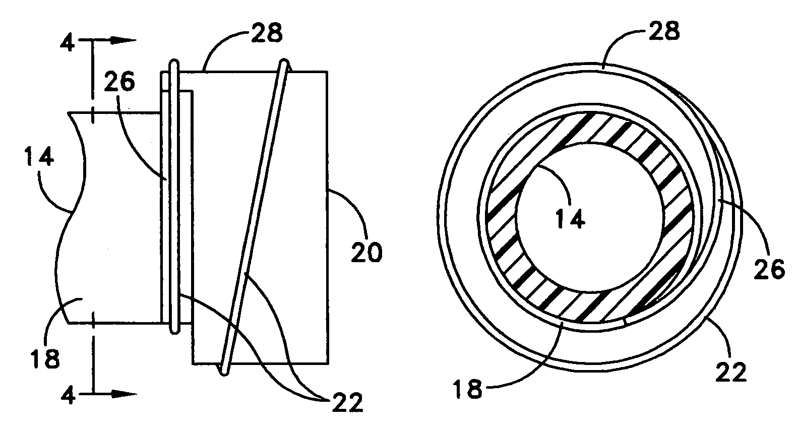
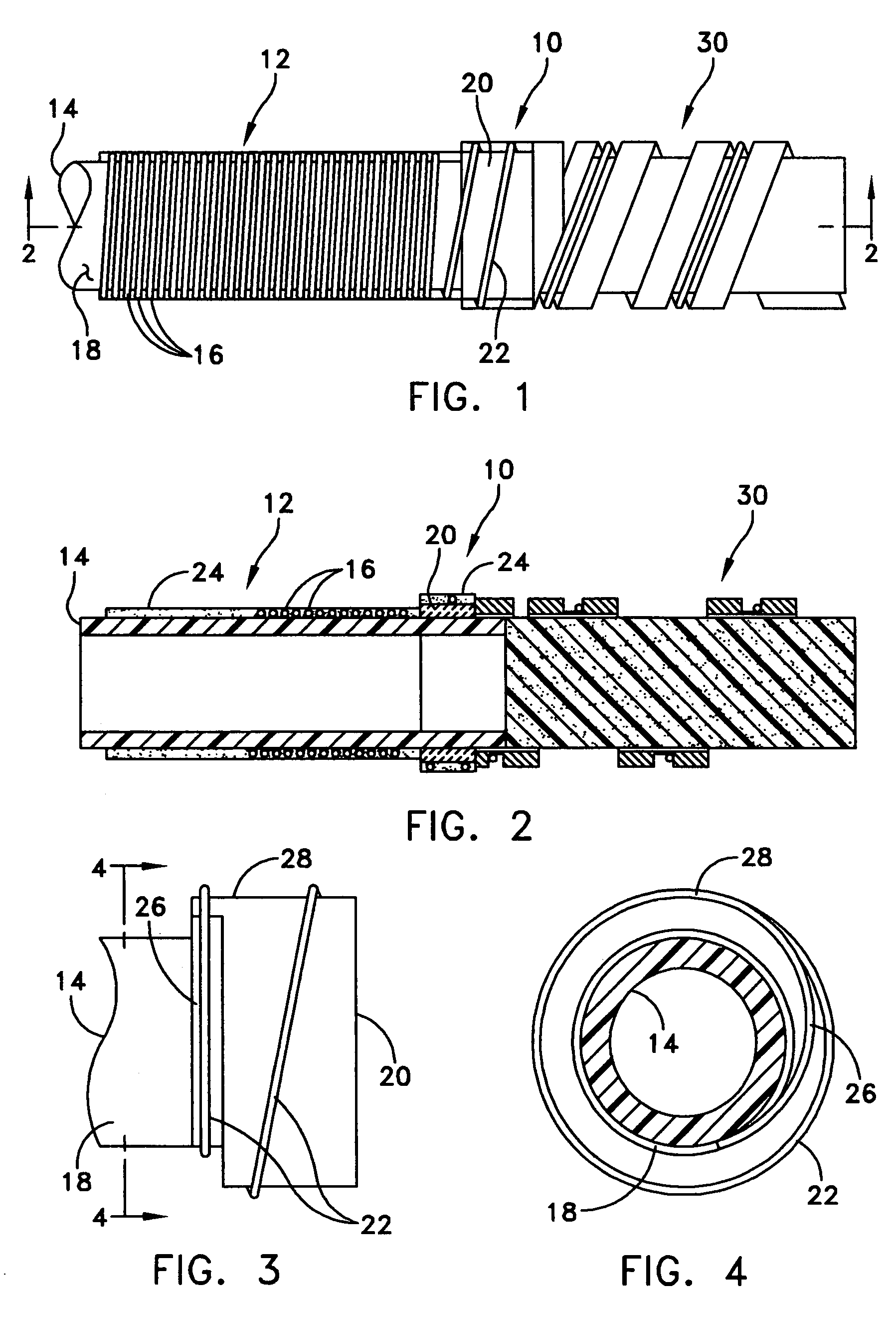
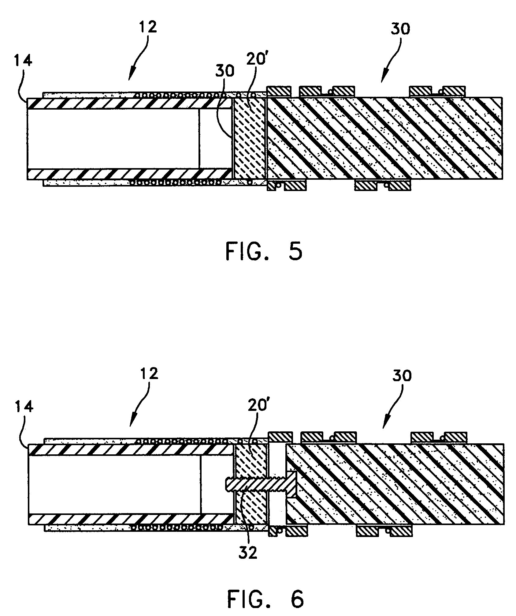
[0022]A thermal compensated fiber Bragg grating (FBG) package 10, FIG. 1, is used with a fiber optic sensor 12, for example, in an underwater hydrophone array. In the exemplary embodiment, the fiber optic sensor 12 includes a generally cylindrical sensor mandrel 14 and an optical fiber 16 wound around an outer surface 18 of the sensor mandrel 14. The sensor mandrel 14 is preferably hollow and made of a compliant material such as plastic designed to be sensitive to pressure changes. Thermally compensated FBG package 10 can also be used with other types of fiber optic sensors.

[0023]The thermally compensated FBG package 10 includes a Bragg grating mount 20 coupled to one end of the sensor mandrel 14. The optical fiber 16 includes a fiber Bragg grating (FBG) portion 22 at one end, which includes the FBG. The FBG acts as a reflector to define the end of the sensor 12 and possibly the beginning of the next sensor. The FBG portion 22 of the optical fiber 16 is preferably wound under tensio...


PUM


Abstract

A thermally compensated fiber Bragg grating package is used with a fiber optic sensor. The package includes a Bragg grating mount connected at each end of a sensor mandrel. An optical fiber is wound around the sensor mandrel and a fiber portion having a Bragg grating therein is wound onto the mount. The mount is made of a rigid material having a negative coefficient of thermal expansion to minimize thermally induced spectral shifts. One example of the material includes zirconium tungstate. A coating material can be used to further adhere the optical fiber to the sensor mandrel and/or to the mount. The mount preferably includes a ramped groove to provide for a smooth transition from the sensor mandrel to the mount.

Description

STATEMENT OF GOVERNMENT INTEREST[0001]The invention described herein may be manufactured and used by or for the Government of the United States of America for governmental purposes without the payment of any royalties thereon or therefore.BACKGROUND OF THE INVENTION[0002](1) Field of the Invention[0003]The present invention relates to fiber optic sensor arrays and, more particularly, to a thermal compensated fiber Bragg grating package for use in a fiber optic sensor array.[0004](2) Description of the Prior Art[0005]The use of fiber optic sensors to determine the presence or magnitude of an external parameter is generally known in the art. A fiber optic hydrophone typically includes a hollow compliant mandrel with an optical fiber wound on the mandrel surface to sense pressure generated by acoustic pressures under water. One type of wavelength and time division multiplexed (WDM / TDM) fiber optic hydrophone array is based upon fiber Bragg gratings (FBGs). FBGs are periodic refractive ...

Claims


Application Information

Patent Timeline
IPC IPC(8): G02B6/34G02B6/00
CPCG01D5/35303G02B6/0218G01L11/025G01D5/35316G01D5/35354
Inventor AMES, GREGORY H.
Owner UNITED STATES OF AMERICA
Why Eureka
Try Eureka