Mass air flow housing for mass air flow sensor

a sensor and air flow technology, applied in the field of mass air flow measurement, can solve the problems of sensor voltage exceeding the range of sensor voltage, sensor not knowing how much fuel to add to the engine, sensor voltage limit, etc., and achieve the effect of reducing air flow and maximizing air flow

Inactive Publication Date: 2007-12-04
TURN5
View PDF21 Cites 6 Cited by
  • Summary
  • Abstract
  • Description
  • Claims
  • Application Information

AI Technical Summary

Benefits of technology

[0010]It is therefore an object of the present invention to provide a replacement housing structure for a mass air flow sensor for an internal combustion engine that maximizes air flow through the housing into the intake manifold of the engine.
[0011]It is a further object of the present invention to provide a replacement housing for a mass air flow meter for an internal combustion engine that decreases air flow as experienced by the mass air flow sensor.
[0012]It is another object of the present invention to provide a replacement housing for a mass air flow meter for an internal combustion engine that reduces back air flow into the calibration tube of the mass air flow sensor.
[0013]The present invention achieves these goals with a housing tube that is installed between the inlet air filter and the throttle body of the engine's inlet air manifold. The housing tube has a maximized area for air flow and a calibration tube with an increased inlet bore to reduce the air flow across the sensor with an angled and restricted outlet that serves to further decrease air flow across the mass air flow sensor and reduces back air flow into the calibration tube.

Problems solved by technology

Without this information, the engine's control module would not know how much fuel to add to the engine.
Large amounts of air flow into the intake of the engine can cause the sensor to exceed its voltage range.
This poses a problem for individuals wishing to increase engine performance by increasing the air flow into the engine's intake manifold.
Often individuals desiring increased engine performance replace factory-installed intake manifold components with components that will allow greater air flow to the engine, but the voltage limit of the mass air flow sensor can be a problem, because when the voltage limit of the mass air flow meter is exceeded, the engine's control module will assume that there is something wrong with the engine, and the vehicle's “check engine” light may come on and there may even be damage to the engine, depending upon how the automobile's computer tries to correct the detected off-nominal situation.
Another problem with the operation of mass air flow sensors is that their readings can be affected by reverse flow or back flow of air in the direction opposite of air intake.
This back flow often causes inaccurate air flow readings because typical mass air flow sensors detect the flow of the air in both the forward and reverse directions relative to air intake.
A disadvantage of this invention was that it required a complex mass air flow housing casting that was not inserted into the main air flow path.

Method used


Image

  • Mass air flow housing for mass air flow sensor
  • Mass air flow housing for mass air flow sensor
  • Mass air flow housing for mass air flow sensor

Examples


Embodiment Construction

[0023]The present invention and its advantages are best understood by referring to the drawings. The elements of the drawings are not necessarily to scale, emphasis instead being placed upon clearly illustrating the principles of the invention. Throughout the drawings, like numerals are used for like and corresponding parts of the various drawings

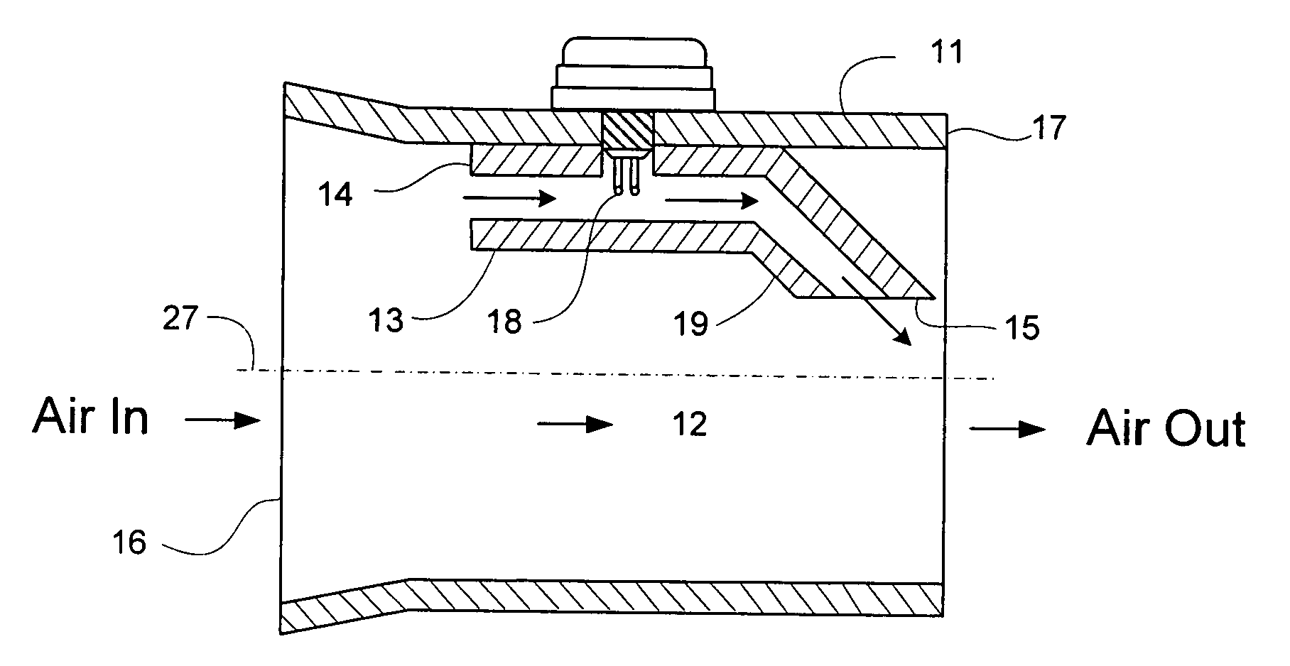
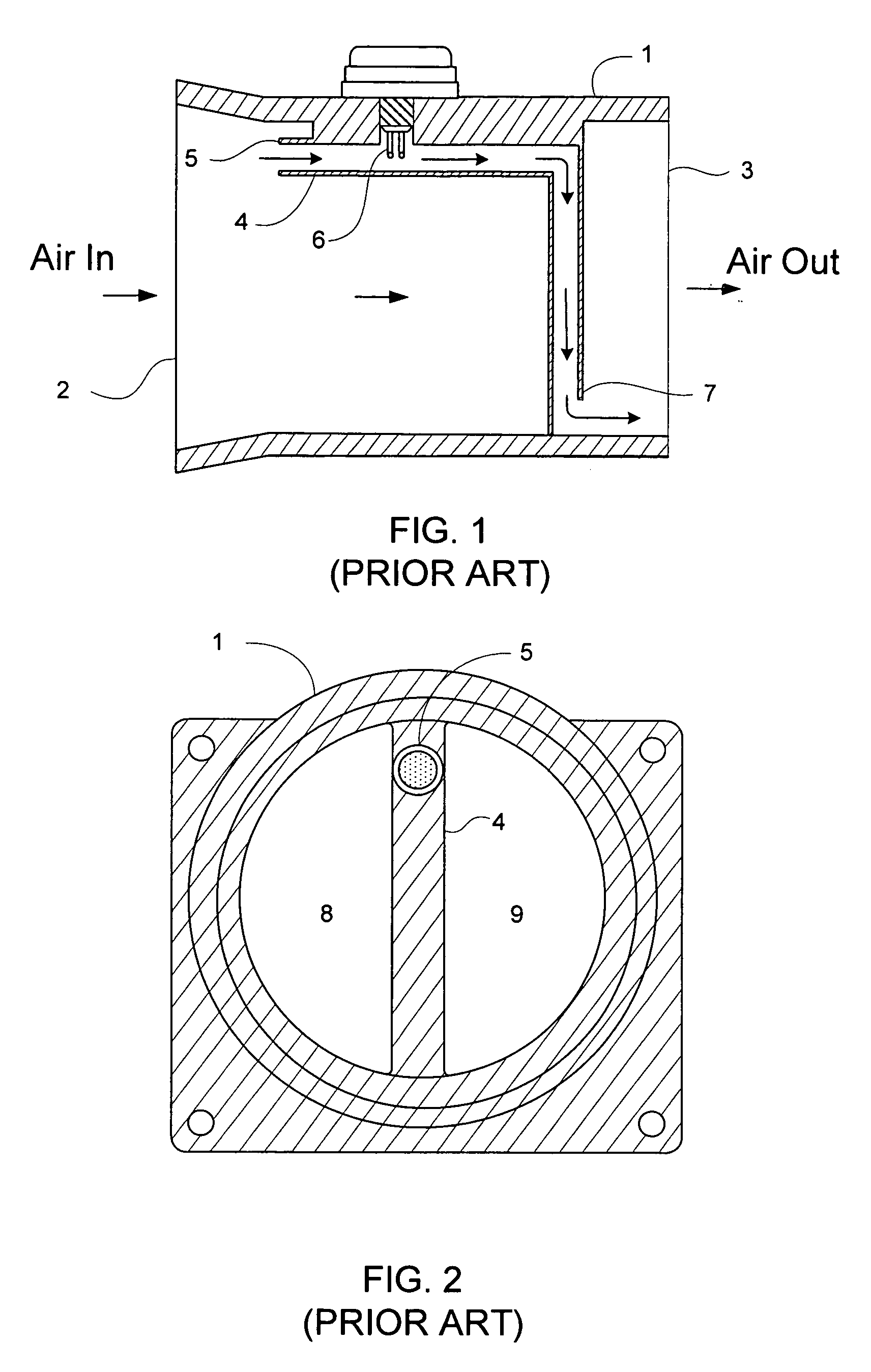
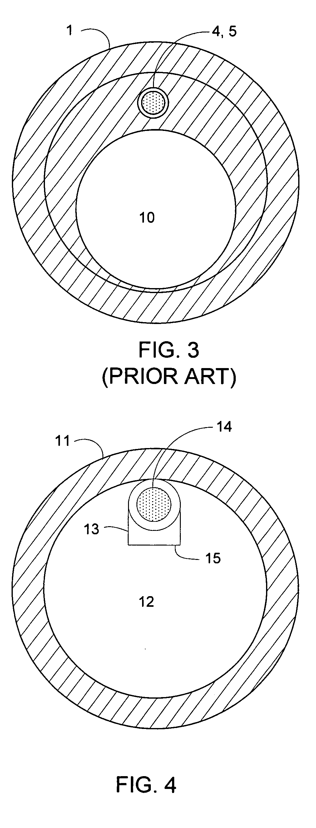
[0024]FIG. 1 is a simplified lengthwise cross section of a prior art mass air flow housing from the intake manifold of a 1996-2001 Ford Mustang®. The mass air flow housing 1 operates by moving air from the inlet 2 of the housing to the outlet 3 of the housing. A bypass calibration tube or sample tube 4 redirects a portion of the air flow through an inlet nozzle 5 and then “stair-steps” down to an outlet nozzle 7. The mass air flow sensor 6 samples the air flow at the first “horizontal” portion of the calibration tube 4. The purpose of the “stair-stepping” of the bypass calibration tube 4 (as opposed to a straight tube) is to decrease the po...


PUM


Abstract

A housing structure for improving air flow to the intake manifold of an internal combustion engine is claimed. The present invention is a replacement part for a factory-installed mass air flow sensor housing and is designed to allow for larger air flow through the housing through the use of a bypass air passage or calibration tube that reduces air flow as experienced by the mass air flow sensor. The calibration tube reduces air flow across the sensor with a larger bore on its inlet and a restriction in its outlet. The calibration tube is angled to reduce back flow from the engine.

Description

BACKGROUND[0001]1. Field of the Invention[0002]The invention relates generally to the field of mass air flow measurement. More particularly, the invention relates to a housing for a mass air flow sensor used for measuring the mass of a medium flowing in a line, in particular the intake air mass of automobile internal combustion engines.[0003]2. Background of the Invention[0004]Mass air flow sensors are used to measure air intake into an automobile's internal combustion engine in order to optimize fuel delivery to the engine. Specifically, the engine's control module needs to know the intake air volume to calculate the engine load so that it can determine how much fuel to inject, when to ignite the cylinder, and when to shift the transmission. Thus the mass air flow sensor is a critically important sensor for achieving optimal engine control. Without this information, the engine's control module would not know how much fuel to add to the engine.[0005]A mass air flow sensor works by c...

Claims


Application Information

Patent Timeline
Patent Type & Authority Patents(United States)
IPC IPC(8): G01F1/68
CPCG01F1/6842
Inventor BENDER, LEE FREDERICK
Owner TURN5
Why Eureka
Try Eureka