
Momentary high pressure valve

a high-pressure valve and valve body technology, applied in the field of valves, can solve problems such as significant challenges, interference or slow down of medical diagnostic procedures, and inability to give injections

Inactive Publication Date: 2007-12-04
SMITHS MEDICAL ASD INC
View PDF46 Cites 29 Cited by
  • Summary
  • Abstract
  • Description
  • Claims
  • Application Information

AI Technical Summary

Benefits of technology

The present invention provides a valve that automatically opens when high pressure is reached, protecting the pressure transducer. It can be used in both power and manually operated systems and is simple and non-bulky. The valve has a housing with three ports, a control wall that normally interrupts a second flow path but flexes to allow the second path to open when high pressure is reached. The control wall flexes back out to shut off the second path when the high pressure ends. The valve can also be used in reverse to control the filling of an injector syringe. The valve element is a flexible wall that flexes into the first flow path to restrict it when high pressure is reached. The valve is made of an elastomeric body with a flexible wall that defines the control wall. Overall, the valve allows for safe and automatic high pressure fluid flow while protecting the pressure transducer.

Problems solved by technology

But blood pressure transducers are very sensitive devices designed for low-pressure environments, such as below 2 psi, thus presenting significant challenges when coupled to the same tubing used for high pressure purposes, such as contrast media injection by way of example.
In that regard, if steps are not taken to protect the pressure transducer, it could be damaged.
A stopcock must be manually manipulated, which can interfere with or slow down the medical diagnostic procedure.
Moreover, if the lever is not rotated to the desired position, the injection may not be given when or as desired or a valid blood pressure reading may not be obtained.
Such manifolds have drawbacks as well, including that they are bulky, have several operating components, and are not well suited to use with manual syringes, for example.

Method used


Image

  • Momentary high pressure valve
  • Momentary high pressure valve
  • Momentary high pressure valve

Examples


Embodiment Construction

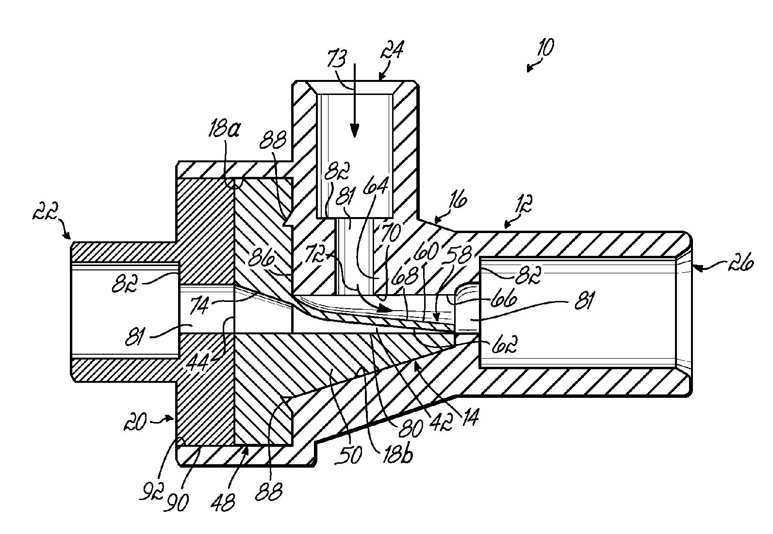
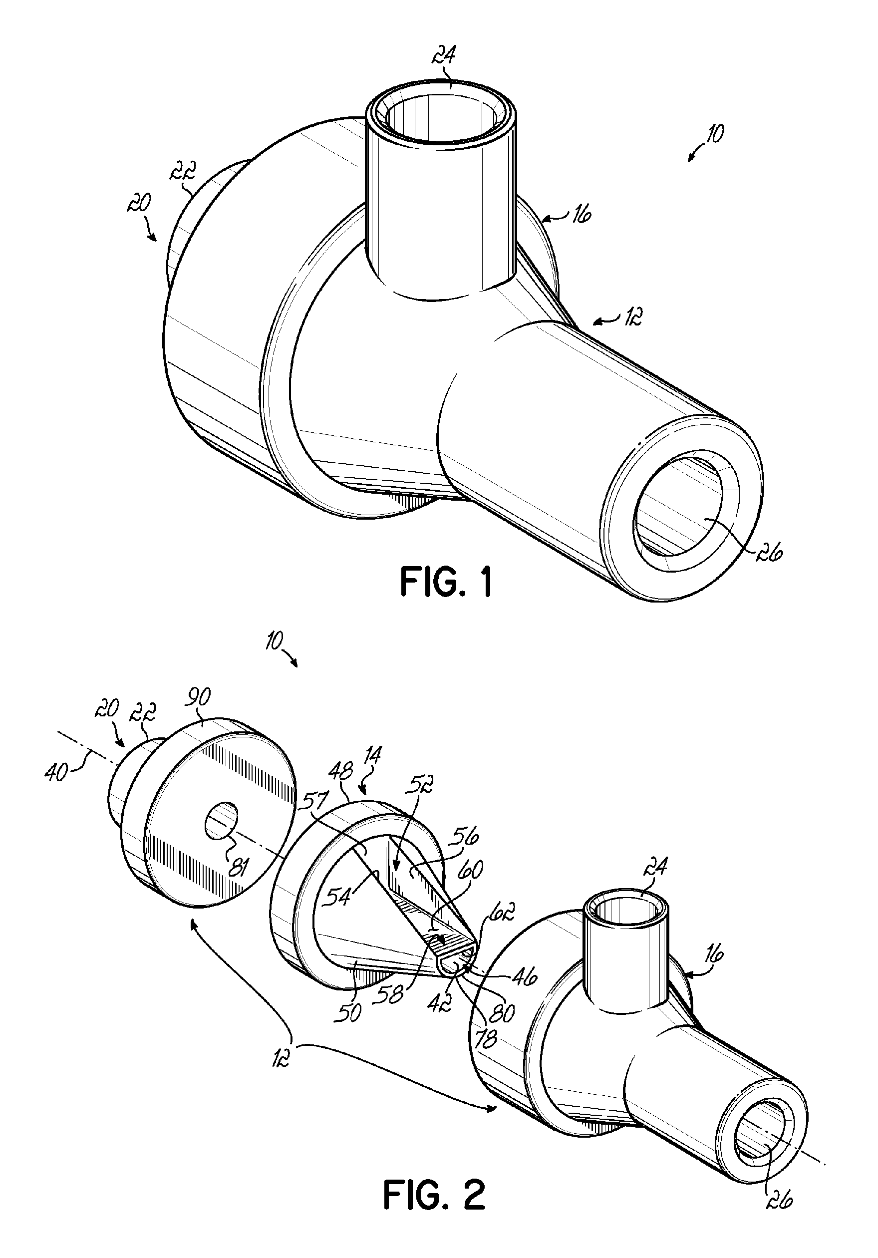
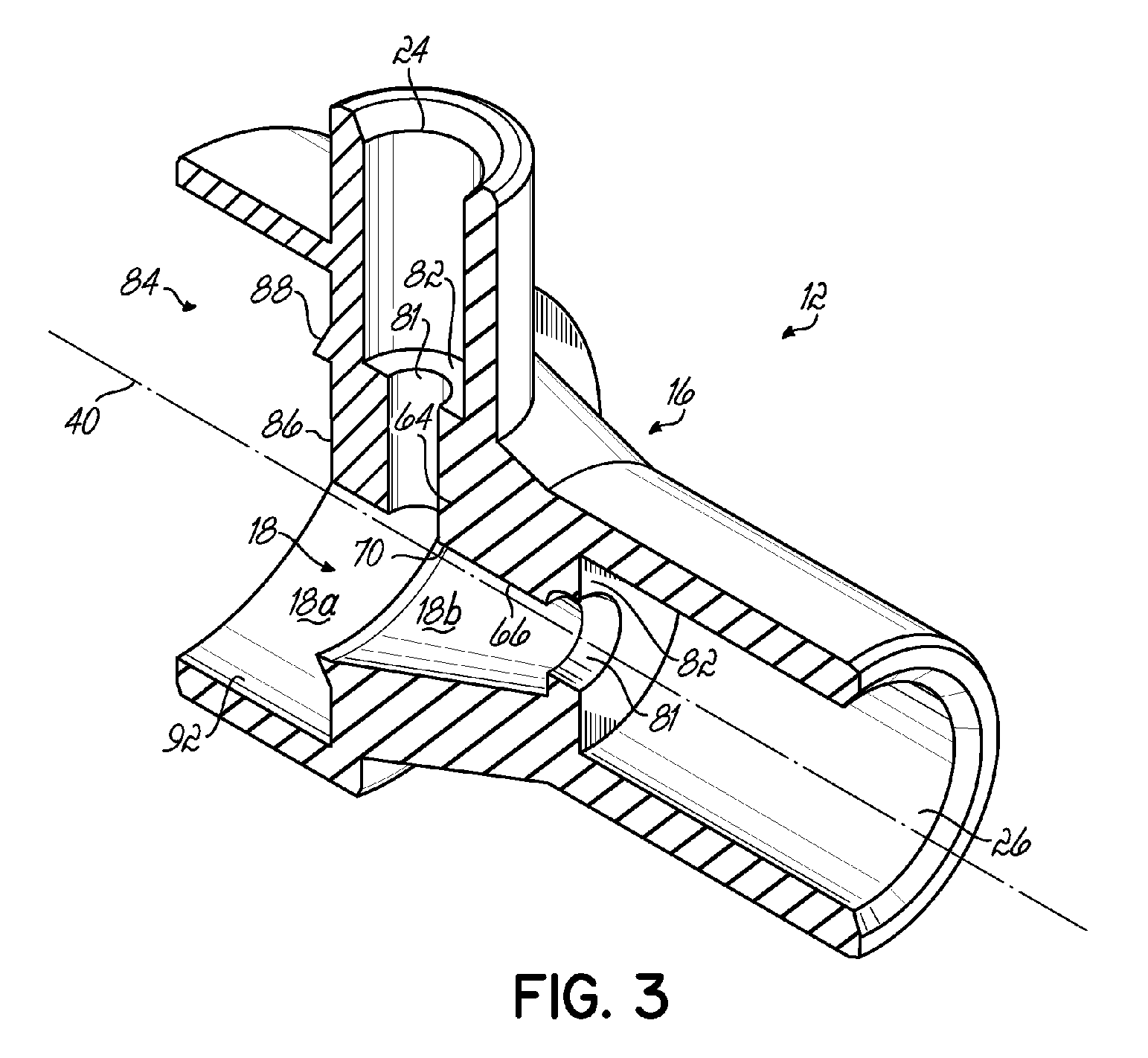
[0020]With reference to FIGS. 1 through 5, there is shown one embodiment of a valve 10 according to the principles of the present invention. Valve 10 has a housing 12 and a valve element 14 situated within housing 12. Housing 12 includes a rigid plastic main body portion 16 defining a chamber 18 sized to receive valve element 14 therein, and a rigid plastic end cap 20 to securably retain valve element 14 within chamber 18.

[0021]Housing 12 includes three ports, 22, 24, 26, with port 22 being designated as a low pressure port and which may be coupled to a low pressure operating device such as a pressure transducer 30 (FIG. 6), port 24 being designated as a high pressure port and which may be coupled to a high pressure generating source such as an injector syringe 32 (FIG. 6), and port 26 being designated as a common or tubing (or patient tubing) port and which may be coupled to patient tubing 34 (FIG. 6) to communicate with the circulatory system of a patient 36 (FIG. 6). In the embod...


PUM


Abstract

A valve (10) comprises a housing (12) with a valve element (14) which normally fluidicly couples a low pressure operating device, such as a transducer (30) and tubing (34) to be coupled to a patient (36) along a first flow path (42) including a flexible control wall (58) which normally interrupts a second flow path (72) between a high pressure generating source such as an injector syringe (32) and the tubing (34), but which flexes, in response to high pressure excursions from the syringe (32) to allow the second flow path (72) to open as it flexes into the first flow path (42) to thereby restrict same thus providing protection to the transducer (30) during the high pressure excursion from the syringe (32).

Description

FIELD OF THE INVENTION[0001]The present invention relates generally to valves, and more particularly to a valve used in the medical field.BACKGROUND OF THE INVENTION[0002]In the medical field, it is often necessary to couple a length of tubing to a patient's blood vessel so as to dispense fluid into the vessel. Rather than pierce the patient's skin a further time, it is advantageous to use the same tubing for other medical purposes as well. For example, during angiographic procedures and other interventional imaging operations, contrast media is typically injected under high pressure through the tubing to a catheter inserted into an artery to generate a radiographic image of the arterial network or other associated location for diagnostic and treatment purposes. The tubing may also be coupled to a pressure transducer by which to obtain the patient's blood pressure in the artery via the hydrostatic column created within the tubing.[0003]Contrast media injection typically requires ext...

Claims


Application Information

Patent Timeline
Patent Type & Authority Patents(United States)
IPC IPC(8): F16K11/02
CPCA61M39/223A61M39/02A61M5/007A61M5/1408A61M2230/30A61M2205/3344Y10T137/0379Y10T137/2567Y10T137/2564
Inventor PATZER, CHARLES R.
Owner SMITHS MEDICAL ASD INC
Learn More