Surge relief valve

a valve and valve body technology, applied in the direction of valve operating means/releasing devices, functional valve types, sealing, etc., can solve the problems of major damage, severe damage to liquid product pipelines, flanges, valves, etc., to eliminate or reduce the effect of reducing the incidence of piston oscillation

Active Publication Date: 2007-12-04
FLOW SAFE
View PDF14 Cites 44 Cited by
  • Summary
  • Abstract
  • Description
  • Claims
  • Application Information

AI Technical Summary

Benefits of technology

[0006]It is a general object of this invention to provide a surge relief valve assembly for rapid relief of excess pressure in liquid systems, whereby main valve set pressure and closing pressure are established solely by a fixed pressure of a suitable gas present in the dome region of the main valve, and whereby system relief can commence at the instant that system fluid pressure acting on the main seat area results in a force on the main piston greater than the opposing force exerted by dome gas pressure at the top of the piston.
[0009]A further object of the invention is to dampen main valve piston movements, particularly upon closing, and eliminate or reduce the incidence of piston oscillations within the surge relief valve through the use of a nonmetallic wedge ring that bears on the piston liner with pressure-induced frictional forces.

Problems solved by technology

While these types of relief valves have proven effective in applications where the fluid product is a gas, they are not suitable for use in some liquid applications, e.g., oil supply lines.
The magnitude of surge pressures vary—some are virtually undetectable, while others are severe enough to cause major damage.
These propagating waves, either increasing or decreasing rapidly, are commonly known as hydraulic transient surges or water hammers that can cause severe damage to liquid product pipelines, vessels, flanges, valving, and associated equipment.
Pilot operated safety relief valves don't operate quickly enough to open and relieve the pressure.

Method used


Image

  • Surge relief valve
  • Surge relief valve
  • Surge relief valve

Examples


Embodiment Construction

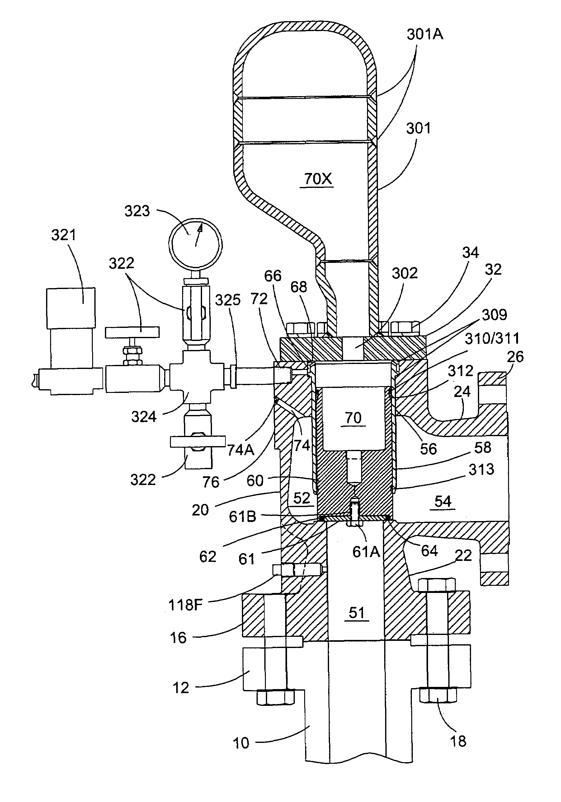
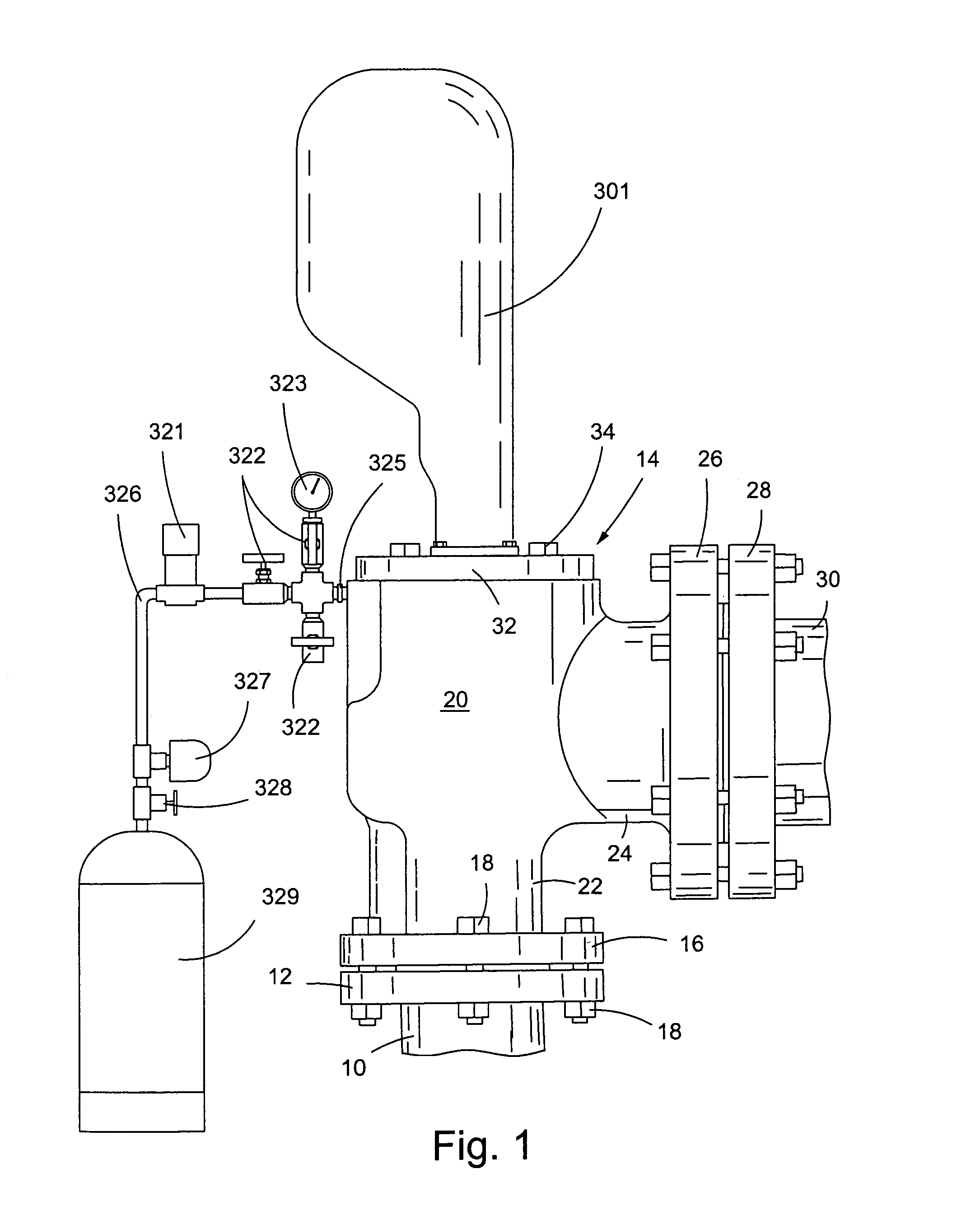
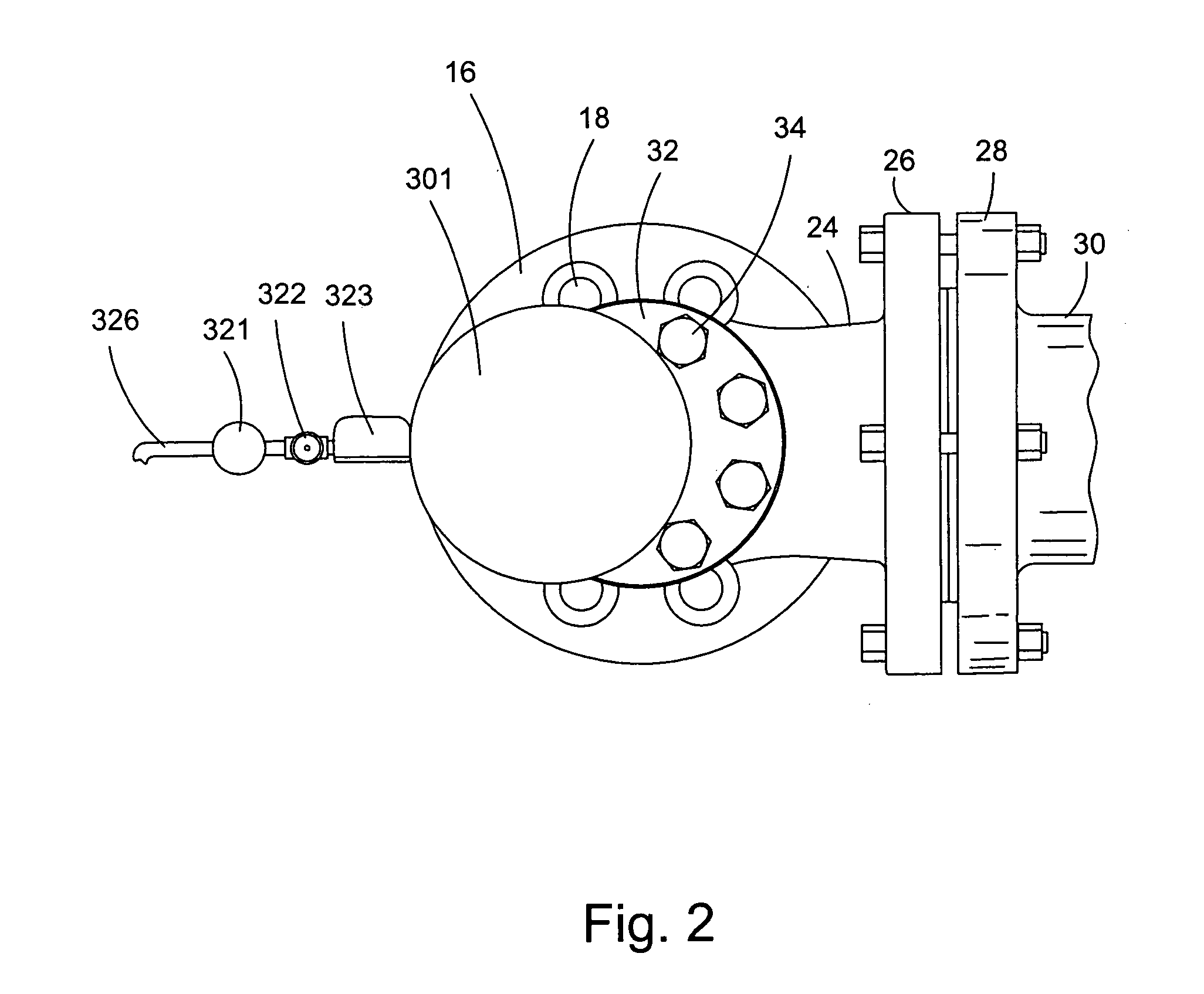
[0017]In the description that follows, the terms “upwardly” and “downwardly” are relative, and refer to the perspective on a viewer facing the invention illustrated in FIGS. 1 and 3. Referring now to the drawing for a better understanding of this invention, and more particularly to the embodiment shown in FIGS. 1-3, a surge relief valve assembly 14 is illustrated in a pressure relief system, including a pipeline, vessel, or tank having an inlet generally indicated at 10 with a flange 12 thereon. The surge relief valve assembly has a lower flange 16 connected to upper system flange 12 by suitable bolt and nut combinations shown at 18. The main body 20 of the assembly has an inlet 22 and outlet 24. A threaded port normally used with other applications of this main valve body generally contains plug 118F. Outlet 24 has a flange 26 that can be connected to an outlet flange 28 and pipe 30 in a similar fashion as inlet flange 16. Fluids flow through the valve from inlet area 51 to outlet ...


PUM


Abstract

A surge relief valve comprising a main valve body having a dome port and an inlet port. The inlet port is in fluid communication with a first fluid. The invention further includes a dome reservoir connected to the main valve body via the dome port and arranged to hold a second fluid, a piston located in the main valve body, the piston in fluid communication with the reservoir, and a dampening ring positioned around the circumference of the piston operatively arranged to dampen the piston, wherein the first fluid exerts an upward force on the piston, the second fluid exerts a downward force on the piston, and the piston is arranged to move in response to a differential in the upward and downward forces, wherein the first and second fluids are isolated from one another.

Description

FIELD OF THE INVENTION[0001]This invention relates to a surge relief valve in a safety relief system for a pressure vessel, more particularly to an improved surge relief valve for use in liquid product pipelines, and, even more particularly, to a surge relief valve having a dome gas-filled reservoir arranged to bias the main valve closed until a set relief pressure is sensed, and then to open to relieve the overpressure, and finally to force the main valve to close when the overpressure has dissipated. The present invention is an improvement over the invention disclosed and claimed in U.S. Pat. No. 5,842,501, issued Dec. 1, 1998, and incorporated herein by reference.BACKGROUND OF THE INVENTION[0002]Heretofore, pilot operated safety relief valves have been provided in pressure relief systems. Examples of prior art pilot operated relief valves are disclosed in U.S. Pat. No. 4,848,397 dated Jul. 18, 1989, and U.S. Pat. No. 5,842,501, dated Dec. 1, 1998. While these types of relief valv...

Claims


Application Information

Patent Timeline
Patent Type & Authority Patents(United States)
IPC IPC(8): F16K17/02G05D16/10
CPCF16K17/02Y10S277/916Y10S277/946Y10T137/0396Y10T137/7762Y10T137/7781Y10T137/785Y10T137/7905
Inventor MARTIN, JEFFREY R.OSTROOT, JOHN W.
Owner FLOW SAFE
Why Eureka
Try Eureka