Isolator mount for shock and vibration mitigation

a technology of isolation mount and shock and vibration, which is applied in the direction of shock absorbers, machine supports, mechanical apparatus, etc., can solve the problems of increasing the cost of replacement, requiring frequent replacement, and the loss of damping capacity of passive mounts comprised of rubber and metal in ship-based applications, so as to achieve the effect of reducing shock and vibration

Inactive Publication Date: 2007-12-04
BOWER BRUCE +1
View PDF20 Cites 11 Cited by
  • Summary
  • Abstract
  • Description
  • Claims
  • Application Information

AI Technical Summary

Benefits of technology

[0009]An object of the present invention is a robust passive damping device capable of mitigating shocks and...

Problems solved by technology

Furthermore, energy dissipation mechanisms employed within presently known devices quickly degrade with use thereby requiring frequent replacement.
For example, passive mounts comprised of rubber and metal rap...

Method used


Image

  • Isolator mount for shock and vibration mitigation
  • Isolator mount for shock and vibration mitigation
  • Isolator mount for shock and vibration mitigation

Examples


Embodiment Construction

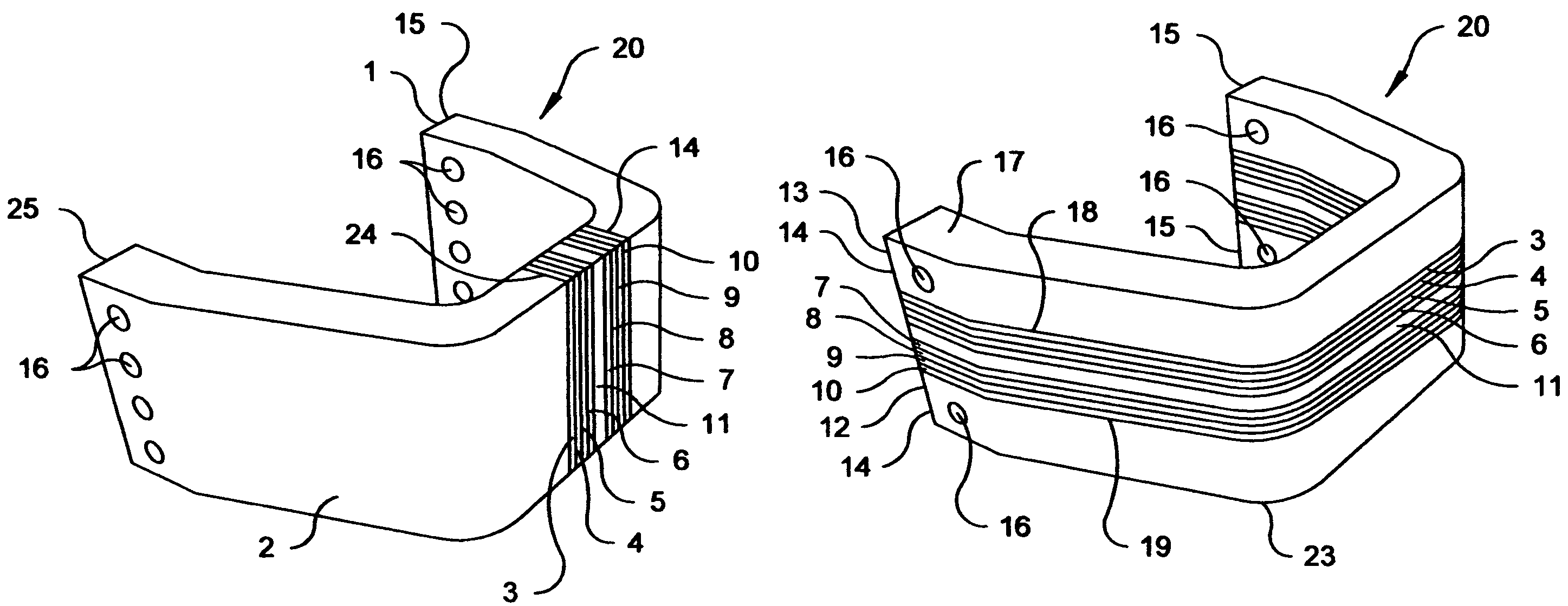
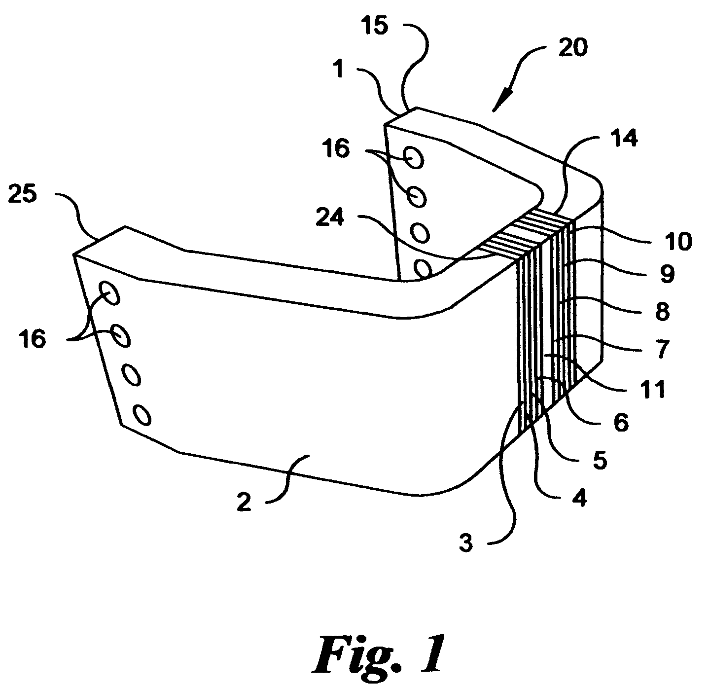
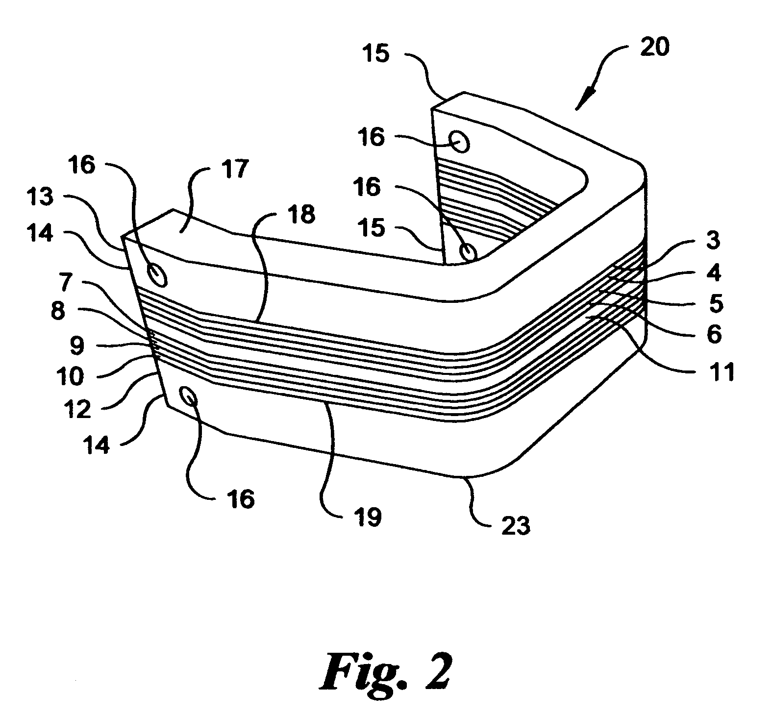
[0044]Referring now to FIG. 1, a C-mount isolator 20 is shown for one embodiment of the present invention including a plurality of energy dissipating layers 3-10 which completely bisect the C-mount isolator 20 along the width of the C-mount isolator 20. Although eight energy dissipating layers 3-6 and 7-10 are shown disposed about the bond layer 11 in FIG. 1, embodiments may include two or more such layers.

[0045]The C-mount isolator 20 comprises a first L-shaped bracket 1 and a second L-shaped bracket 2 with two or more energy dissipating layers 3-10 and a bond layer 11 disposed there between. First and second L-shaped brackets 1, 2 are arranged in a symmetrical fashion about the energy dissipating layers 3-10 and bond layer 11 to achieve the C-shaped structure of the C-mount isolator 20.

[0046]Energy dissipating layers 7-10 and 3-6 are applied onto the first and second L-shaped brackets 1, 2, respectively, via methods understood in the arts. The first L-shaped bracket 1 includes one...


PUM

PropertyMeasurementUnit
Thicknessaaaaaaaaaa
Magnetic energyaaaaaaaaaa
Mechanical propertiesaaaaaaaaaa

Abstract

A passive isolator mount capable of dissipating shocks and vibrations as either heat or magnetic energy is presented. The passive isolator includes a pair of L-shaped or C-shaped brackets capable of withstanding repeated deflections and strains, energy dissipating layers disposed along each bracket, and a bond layer. The energy dissipating layers are composed of a rare earth element or alloy, a ferromagnetic shape alloy, a magnetic shape memory alloy, a magnetostrictive alloy, a magneto-mechanical alloy, a super-elastic alloy, or a combination thereof. The bond layer is disposed between and adheres one energy dissipating layer along a first bracket to an energy dissipating layer along a second bracket so that the resultant passive isolator is C-shaped. Energy dissipating and bond layers completely bisect the passive isolator either widthwise through the thickness of the L-shaped brackets or lengthwise through the thickness of the C-shaped brackets.

Description

CROSS-REFERENCE TO RELATED APPLICATIONS[0001]This application is a continuation-in-part application of U.S. Non-Provisional application Ser. No. 11 / 111,370, filed Apr. 21, 2005 now abandoned, which is a divisional application of co-pending U.S. Non-Provisional application Ser. No. 10 / 188,446, filed Jul. 2, 2002, and claims the benefit of U.S. Provisional Application No. 60 / 302,579, filed Jul. 2, 2001. The subject matters of the prior applications are incorporated in their entirety herein by reference thereto.FEDERALLY SPONSORED RESEARCH OR DEVELOPMENT[0002]None.BACKGROUND OF THE INVENTION[0003]1. Field of the Invention[0004]The present invention generally relates to an isolator mount. Specifically, the isolator mount includes a plurality of energy dissipating elemental and / or alloy layers which bisect the mount so as to impede and dissipate shocks and vibrations which traverse the mount.[0005]2. Related Arts[0006]Naval ships employ a wide variety of isolator mounts to impede acousti...

Claims


Application Information

Patent Timeline
IPC IPC(8): F16M1/00
CPCF16F1/027F16F3/023F16F2224/0283F16F2224/0258F16F2224/0208
Inventor BOWER, BRUCEKNOWLES, GARETH
Owner BOWER BRUCE
Why Eureka
Try Eureka