Refractory metal core cooling technologies for curved leading edge slots

Active Publication Date: 2007-12-04
RTX CORP
View PDF6 Cites 26 Cited by
  • Summary
  • Abstract
  • Description
  • Claims
  • Application Information

AI Technical Summary

Problems solved by technology

Airfoil leading edge cooling is critical as there are considerable amounts of oxidation distress observed in almost all operating airfoil portions of turbine engine components.

Method used


Image

  • Refractory metal core cooling technologies for curved leading edge slots
  • Refractory metal core cooling technologies for curved leading edge slots

Examples


Embodiment Construction

)

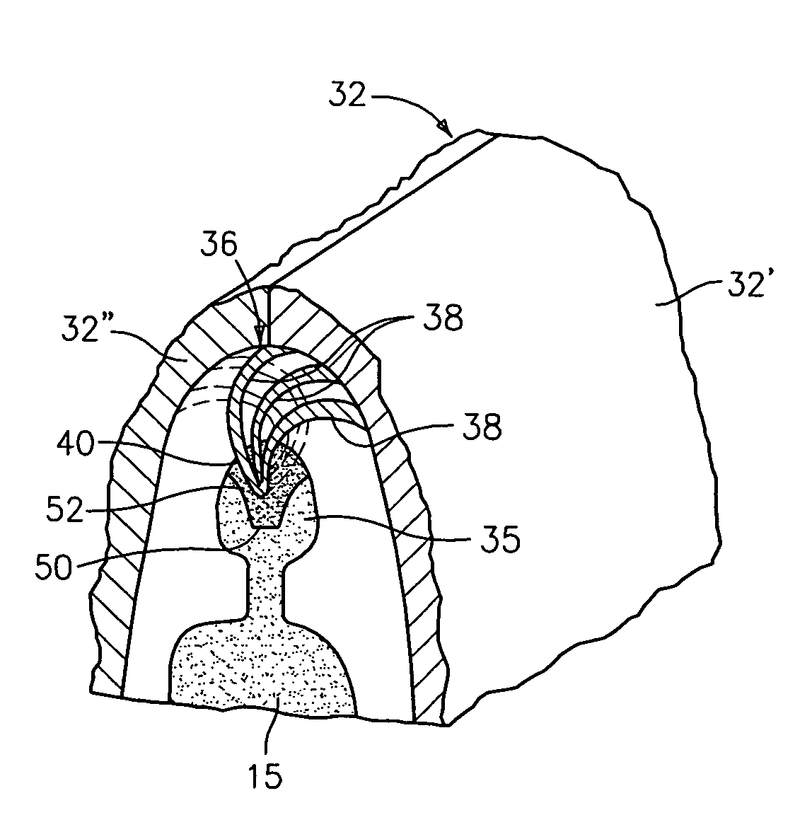
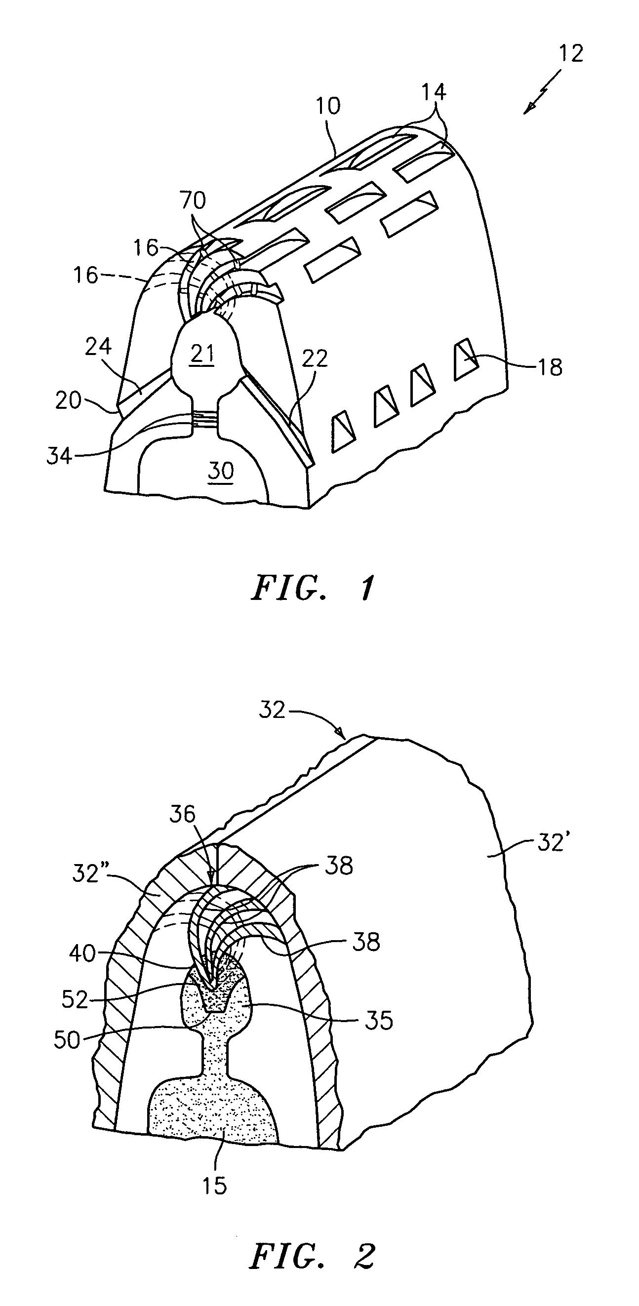
[0011]Referring now to the FIG. 1 of the drawings, there is illustrated a leading edge portion 10 of an airfoil portion 12 of a turbine engine component, such as a turbine blade, a turbine vane, and a seal. As can be seen from FIG. 1, the leading edge portion 10 preferably has a staggered arrangement of leading edge slots 14 with the slots preferably being arranged in a plurality of rows. While FIG. 1 shows slots as being present on the suction side of the leading edge, similarly arranged slots may be present on the pressure side of the leading edge. Each of the leading edge slots 14 communicates with a source of a cooling fluid, such as turbine engine bleed air, via a central core element 21 and a plurality of curved passageways 16 which communicate with the central core element 21 so as to provide a film of cooling fluid over the external surfaces of the airfoil portion 12. As can be seen from FIG. 1, the curved fluid passageways 16 may extend in a plurality of directions.

[0012]I...


PUM

PropertyMeasurementUnit
refractoryaaaaaaaaaa
pressureaaaaaaaaaa
shapeaaaaaaaaaa

Abstract

A turbine engine component has an airfoil portion with a leading edge portion. The leading edge portion includes a plurality of staggered holes for causing fluid to flow over a surface of the airfoil portion. A method for forming the leading edge portion using refractory metal core technology is described.

Description

BACKGROUND OF THE INVENTION[0001](1) Field of the Invention[0002]The present invention relates to a process for forming leading edge portion of an airfoil portion of a turbine engine component and a turbine engine component formed thereby.[0003](2) Prior Art[0004]Airfoil leading edge cooling is critical as there are considerable amounts of oxidation distress observed in almost all operating airfoil portions of turbine engine components. While leading edge cooling is known in the art, a better leading edge cooling scheme is desirable—particularly one which reduces the amount of distress seen in the operating airfoil portions.SUMMARY OF THE INVENTION[0005]In accordance with the present invention, a leading edge portion for an airfoil portion of a turbine engine component is provided. The leading edge portion broadly comprises a plurality of staggered holes for causing a film of cooling fluid to flow over a surface of the airfoil portion.[0006]Further in accordance with the present inv...

Claims


Application Information

Patent Timeline
Patent Type & Authority Patents(United States)
IPC IPC(8): F01D5/18
CPCB22C9/103B22C9/108B22C9/126F01D5/186F01D5/187F05D2240/121Y10T29/49341F05D2250/18F05D2230/21F05D2250/71F05D2260/2214F05D2250/13F05D2240/303F01D5/12F01D5/18
Inventor CUNHA, FRANKABDEL-MESSEH, WILLIAM
Owner RTX CORP
Why Eureka
Try Eureka