
Combined vertical and horizontal rope climbing apparatus

a rope pulling and rope technology, applied in the field of rope pulling equipment, can solve the problems of reducing the number of gyms used today, and reducing the number of gyms

Inactive Publication Date: 2007-12-04
REYNOLDS LYNN +1
View PDF10 Cites 21 Cited by
  • Summary
  • Abstract
  • Description
  • Claims
  • Application Information

AI Technical Summary

Benefits of technology

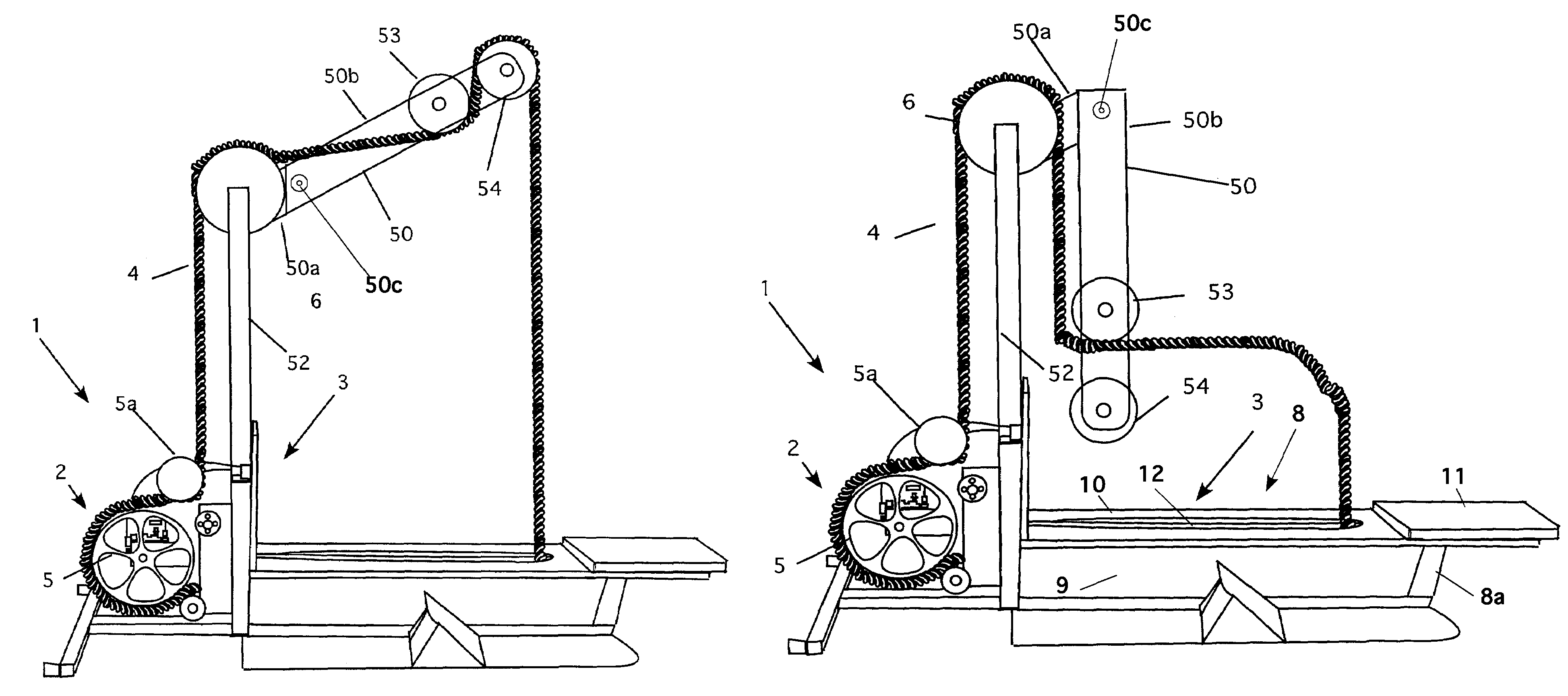
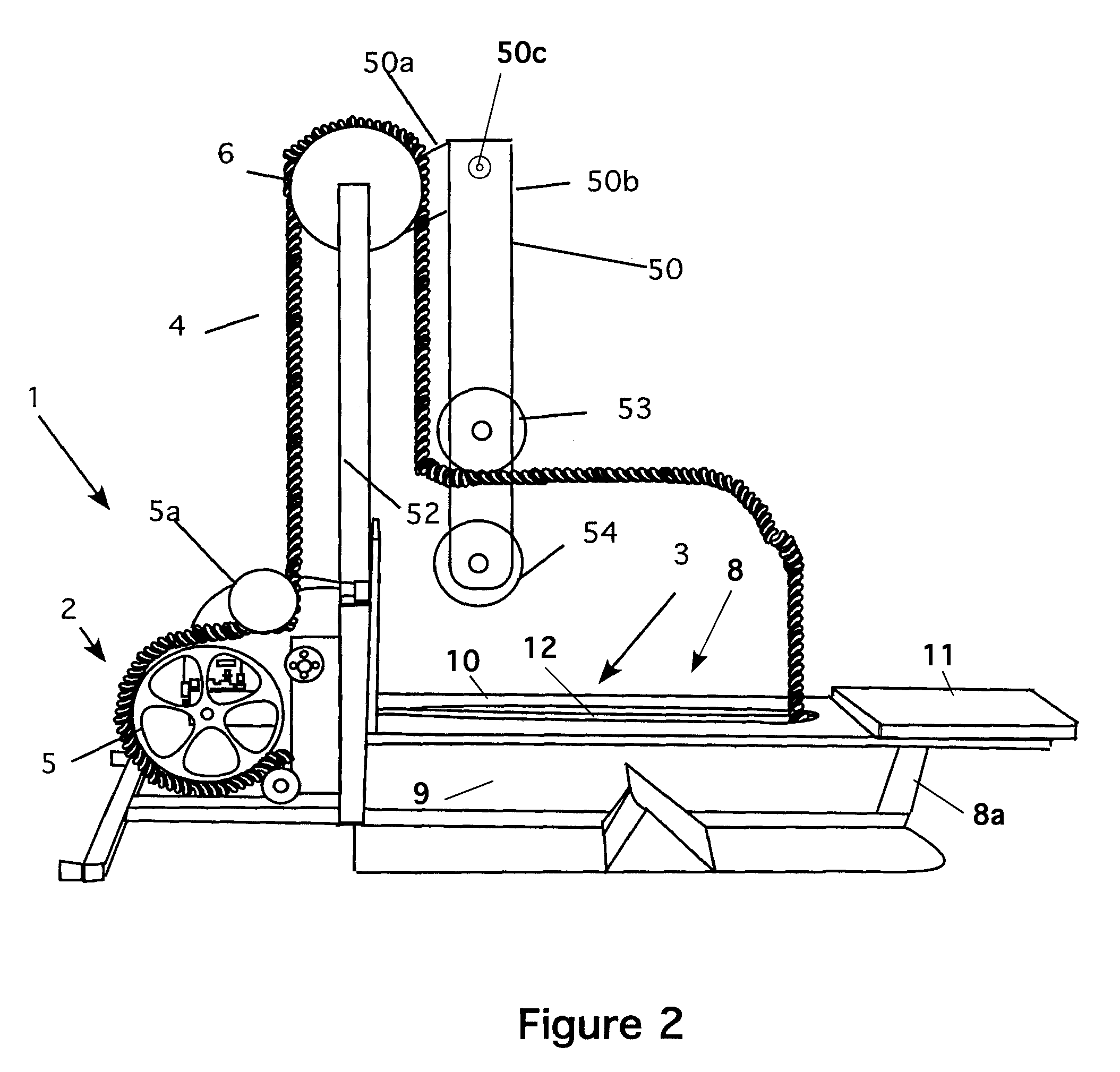
[0012]In the horizontal mode, the rotating boom is rotated down so that it is parallel to the vertical frame. The rope follows the downward run of the boom. Here, however, instead of passing over the second guide pulley, the user pulls the rope back using the first guide pulley as a guide. As before, the rope passes down through the trough in the horizontal frame and then back to the braking pulley. In this way, the user can use the machine as a horizontal rope-pulling machine.

Problems solved by technology

There are two problems with the traditional fixed rope as an exercise tool.
First, there are few buildings used for gyms today that have high enough ceilings.
Second, a 20-foot length of rope does not provide enough sustained effort to enable someone skilled in rope pulling exercise to receive a sufficient workout.
The problem with this machine is that it is bulky with the treadmill.
Moreover, although this device can simulate a tug-of-war, such a simulation is not the best exercise that can be obtained using a pulled rope.
Thus, it appears that when not in use, the rope is left lying on the treadmill, which is a tripping hazard.
This can lead to discomfort when the rope is under tension, because the loop may close on the user's hands.
The problem with this machine is that the user must keep the rope to one side of the user's body.
This is uncomfortable and may cause irritation and chaffing during use.
Although the vertical and horizontal machines exist, no machine combines the features of vertical and horizontal machines into one single machine.

Method used


Image

  • Combined vertical and horizontal rope climbing apparatus
  • Combined vertical and horizontal rope climbing apparatus
  • Combined vertical and horizontal rope climbing apparatus

Examples


Embodiment Construction

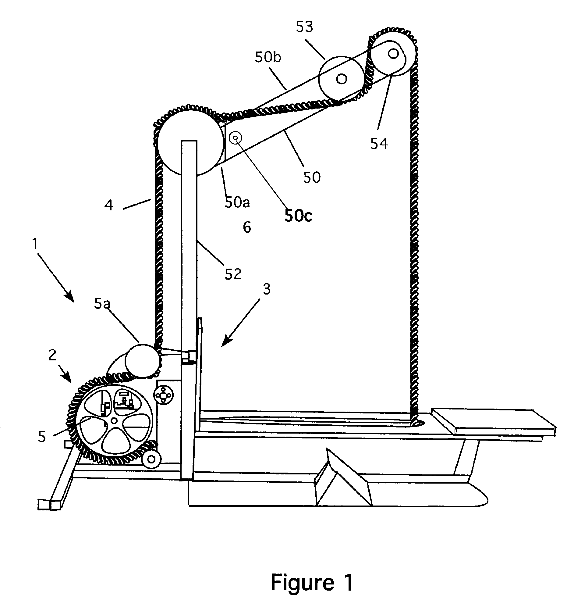
[0019]Referring now to FIG. 1, the invention 1, is shown. The invention is a combination horizontal and vertical rope-pulling device. The machine uses a hydraulic braking assembly 2 (see FIGS. 2, 4, and 5) that is mounted on a frame 3 to support an endless rope 4 that is placed over a number of pulleys. The rope 4 passes over the pulley 5, which is the breaking pulley. The rope then passes back, over a transition pulley 5a. It rises vertically to an upper pulley 6. A pivoting boom 50 is attached at the top of the frame. The boom has a fixed member 50a that spaces the rotating boom 50b from the vertical frame 52. A pivot point 50c is also shown (see also FIG. 2). In the vertical mode, as shown in FIG. 1, the rotating boom 50b is positioned at an angle and extends rearward from the vertical frame 52. The rope passes over the upper pulley 6, and then runs back to the first guide pulley 53. It then runs up over the second guide pulley 54, where it then drops down to the horizontal frame...


PUM


Abstract

A combination horizontal and vertical rope-pulling device that uses a hydraulic braking assembly that is mounted on a vertical frame to support an endless rope that is placed over a number of pulleys. A pivoting boom is attached at the top of the frame. In the vertical mode, the rotating boom is positioned at an angle extending rearward from the vertical frame. The rope passes over a number of pulleys to simulate a vertical rope for climbing. In the horizontal mode, the rotating boom is rotated down so that it is parallel to the vertical frame. The rope follows the downward run of the boom and around the pulleys. In this way, the user can use the machine as a horizontal rope-pulling machine.

Description

CROSS REFERENCE TO RELATED APPLICATIONS[0001]This application claims the benefit under 35 U.S.C. 119(e) based on Provisional Application No. 60 / 609,894, filed Sep. 14, 2004.STATEMENT REGARDING FEDERALLY SPONSORED RESEARCH AND DEVELOPMENT[0002]Not ApplicableBACKGROUND OF THE INVENTION[0003]1. Field of the Invention[0004]This invention relates to rope pulling apparatus and particularly to a combination vertical and horizontal rope pulling apparatus using endless ropes.[0005]2. Description of the Prior Art[0006]Pulling ropes have been a part of fitness gyms for many years. Rope pulling is an excellent exercise for the wrists, hands and upper body. Traditionally, these ropes have been long (20 foot) lengths of rope that were suspended from a gym ceiling. There are two problems with the traditional fixed rope as an exercise tool. First, there are few buildings used for gyms today that have high enough ceilings. Second, a 20-foot length of rope does not provide enough sustained effort to ...

Claims


Application Information

Patent Timeline
IPC IPC(8): A63B7/04A63B21/008
CPCA63B7/04A63B23/12A63B21/018A63B7/045A63B23/1209A63B23/03533A63B23/03541A63B21/4043A63B21/4035A63B21/4045
Inventor REYNOLDS, LYNNMAESTAS, JOSEPH F.
Owner REYNOLDS LYNN
Learn More