
Turbo-machine and method for operating the same

a technology of turbines and motors, applied in the direction of machines/engines, nuclear engineering, positive displacement liquid engines, etc., can solve the problems of secondary losses, inability to achieve optimal homogeneous deflection of action fluids, and need a considerable cooling requirement, so as to avoid specific disadvantages of mhd power station concepts, increase the thermal efficiency of turbines, and high process temperatures

Inactive Publication Date: 2007-12-04
SIEMENS AG
View PDF20 Cites 11 Cited by
  • Summary
  • Abstract
  • Description
  • Claims
  • Application Information

AI Technical Summary

Benefits of technology

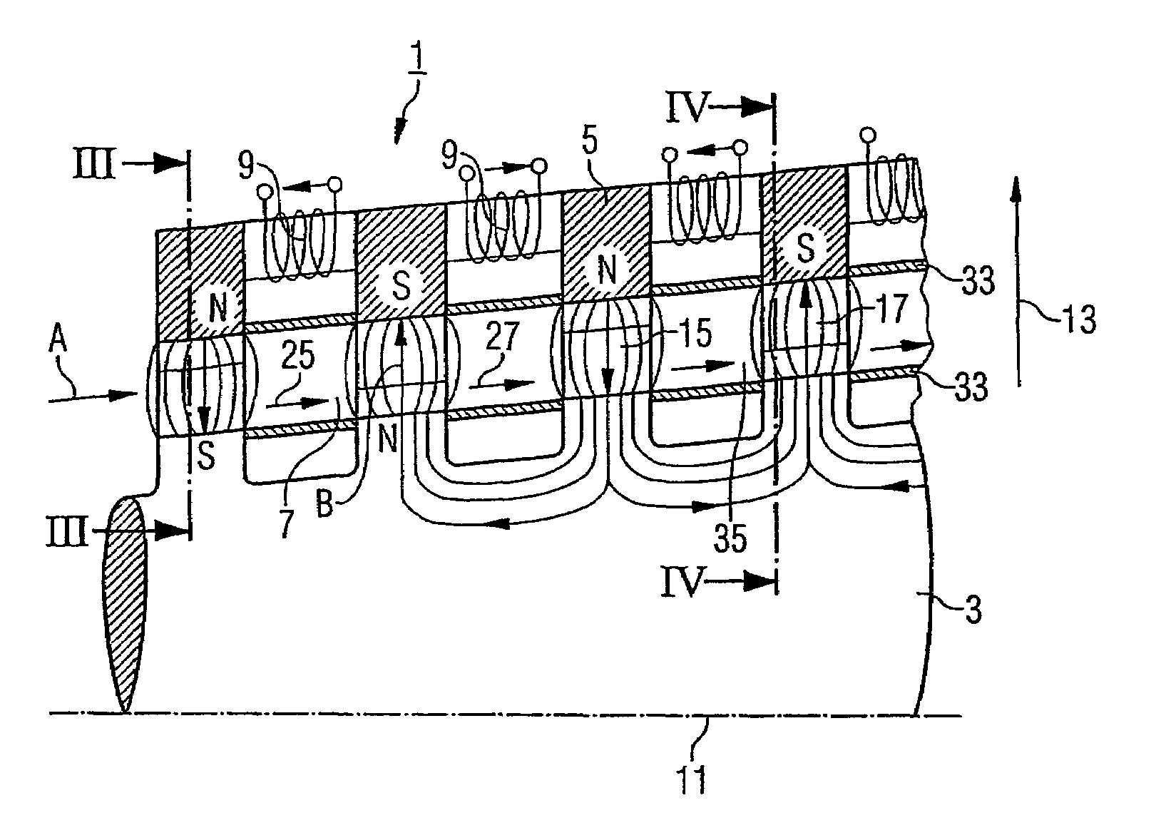
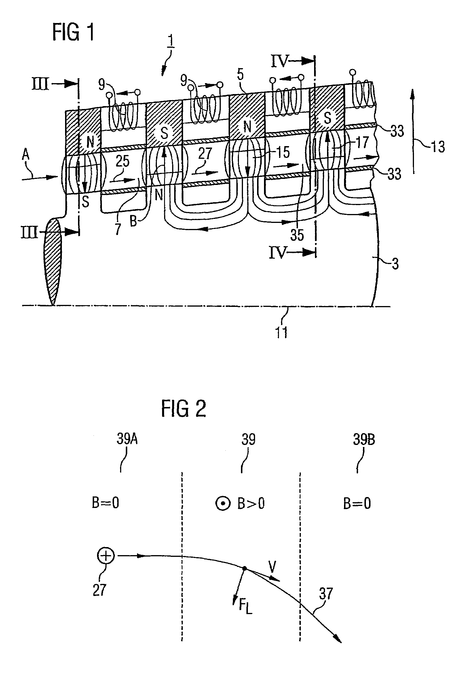
[0017]By means of the magnet, a both time-defined and spatially-defined magnetic field can be generated in the flow duct, thus leading to a defined deflection of charged particles in the action fluid and, on account of a pull effect as a result of pulse transfer, to a deflection of the action fluid itself. Deflection in this case takes place advantageously in the form of deflection planes between rotor and stator which are predetermined by the magnetic field and which possess a limited extent (localization of the magnetic field) in the main flow direction of the action fluid, for example in the axial direction in the case of an axial machine. The provision of a magnetic deflection plane for the charged particles or the action fluid by means of the magnetic field is very similar in its action to a conventional blade cascade: where an axial turbomachine is concerned, for example, a deflection of a predominantly axial flow of the action fluid takes place in a flow with both an axial and a tangential component, this being because of the fact that, on account of the Lorenz force, a tangential component is imparted to the charged particles perpendicularly to the flow direction as a result of the interaction with the magnetic field. This deflection is associated with a conversion of pressure energy of the action fluid into kinetic energy, in a similar way to a guide blade cascade of a conventional turbine. In the same way, it is possible, from a flow of the action fluid with an axial and tangential component, to achieve a conversion into a predominantly axial flow, with kinetic energy being converted into mechanical work, in a similar way to a moving blade cascade of a conventional turbine. Consequently, in a similar way to conventional turbines, a suitable magnetic field configuration, with a magnetic field in the flow duct is generated spatially and, if appropriate, in time by means of the magnet, makes it possible to have a progressive expansion of the action fluid, at the same time with the acquisition of mechanical work which can be transmitted in the form of rotational energy to the rotor.
[0019]In a preferred embodiment of the turbomachine, the stator has the magnet. In this case, it is possible to integrate the magnet into the stator, so that the magnetic field generated by the magnet acts into the flow duct. In this case, it is also possible for the stator to have a plurality of magnets, so that the magnetic field can be set highly accurately in spatial terms in the flow duct according to the requirements. In the case of an axial machine, in which the stator conventionally at the same time forms an outer boundary of the flow duct and at the same time can function as an outer casing of the turbomachine, the magnet is advantageously particularly readily accessible for possible maintenance or inspection work or for the mounting of sensors (for example, magnetic field sensors) for the diagnostics of the turbomachine. Furthermore, if a ferromagnetic substance is selected, the stator material may at the same time be used for increasing the magnetic flux density and consequently the magnetic field in the flow duct.
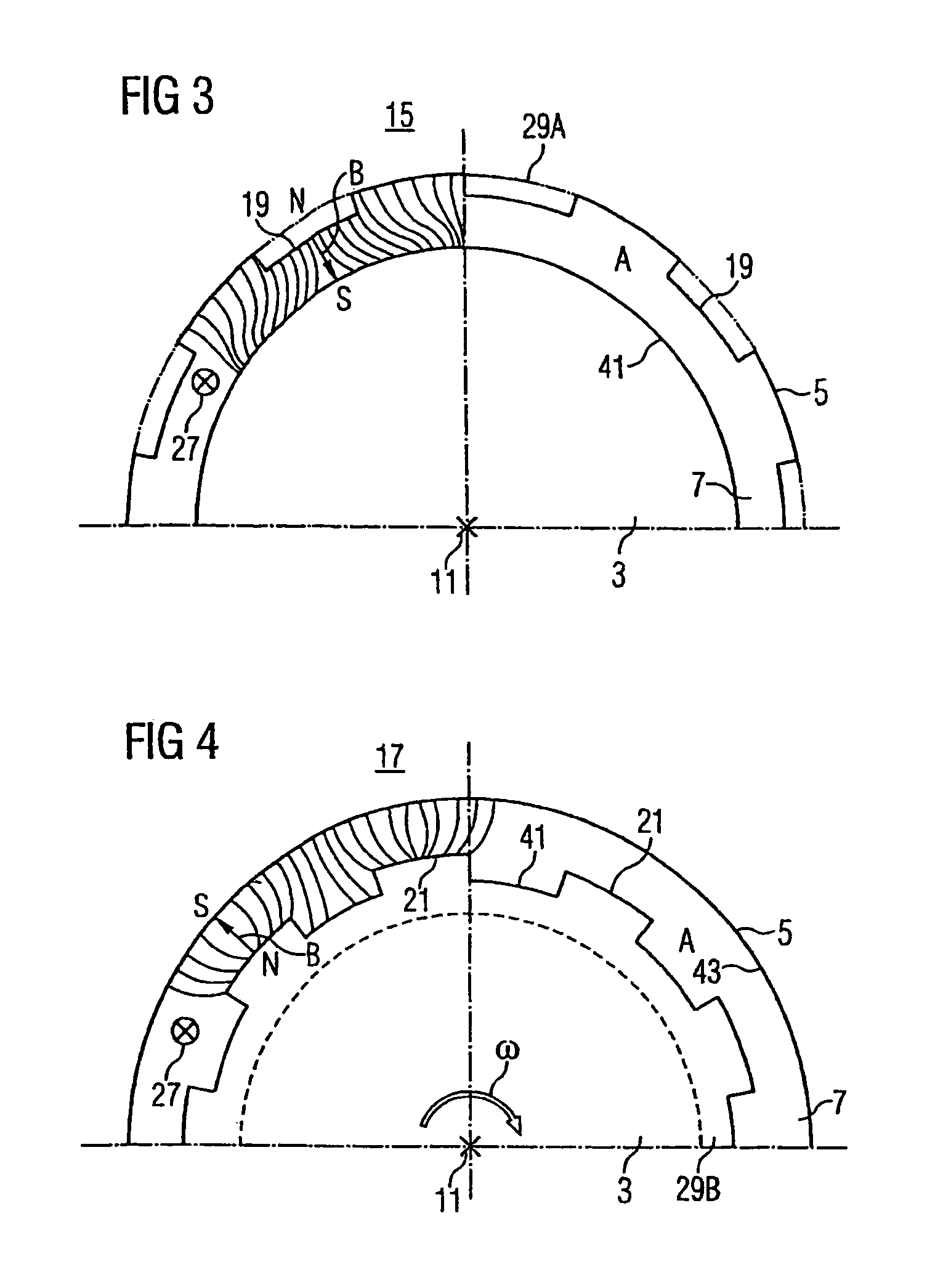
[0030]However, as compared with conventional blading, in the magnetic guide blade of the invention there is advantageously no need for any complex geometry for the projection. The projection may be configured, in terms of its geometry and its magnetic properties of the material, in such a way that the best possible results are achieved, in a similar way to a pole piece. The projection may in this case be adapted in a constructively simple way to the radial symmetry, in particular to the cylinder-envelope-shaped surface contour of the rotor, and consists of a material with high magnetic permeability, in order to achieve correspondingly high magnetic flux densities of the radial deflection magnetic field.
[0034]The radially outwardly extending projection achieves a local increase in the magnetic flux density, that is to say the magnetic flux lines are concentrated in a space between the projection and the stator located opposite the projection in a radial direction. Owing to this configuration, approximately, a magnetic dipole structure is implemented locally, in which case, depending on the selected polarity, magnetic flux lines emerging, for example, from the projection form a magnetic north pole, while the opposite stator surface which the magnetic flux lines enter forms a south pole. The spatial confinement of the field allows an accurately directed deflection of charged particles in the action fluid, so that the moving blade based on the magnetic deflection of charged particles is thereby intimated, in a similar way to conventional turbomachines.
[0045]Also preferably, ions are formed by the ionization of particles in the action fluid during the flow of the latter through the flow duct. The in-situ generation in this case has the advantage that the ions can be generated in an accurately directed manner in the regions where they are also required for performing a magnetic deflection, that is to say in the magnetic guide blade region or the magnetic moving blade region.

Problems solved by technology

Blades for extremely high application temperatures, such as, for example, gas turbine blades, are therefore produced partially from monocrystalline workpieces and, because of the high temperatures of the action fluid, for example of the hot gas, need a considerable cooling requirement.
Furthermore, because of the finite number of blades, there cannot be an optimum homogeneous deflection of the action fluid.
In addition, blade cascades possess a flow resistance, that is to say boundary layers are formed on the blades, which may lead to secondary losses in the following blade cascades.
As already discussed further above, because of the use of high-grade high-temperature materials, blades for use in high-temperature applications are very costly and of limited strength on account of the increased material and manufacturing costs.
In the event of a failure of a blade, for example as a result of a breakaway from the rotor due to an overshooting of the maximum permissible centrifugal force load, considerable consequential damage may occur in the turbomachine.
A further disadvantage of the known bladings is attributable to the gap losses which always occur.
Gap mass flows of action fluid, which pass through between a blade and component located opposite the blade so as to form a gap, result in an efficiency loss (gap loss).
In order to keep the losses as low as possible, the gap mass flow must be limited by means of narrow clearances which are highly complicated to ensure in manufacturing processes.

Method used


Image

  • Turbo-machine and method for operating the same
  • Turbo-machine and method for operating the same
  • Turbo-machine and method for operating the same

Examples


Embodiment Construction

[0058]FIG. 1 shows a detail of a turbomachine 1 which operates according to a magnetohydrodynamic principle. For this purpose, the turbomachine 1 has a rotor 3 extending along an axis of rotation 11. A stator 5 surrounds the rotor 3, so as to be spaced apart concentrically from the latter, over the entire circumference, thus forming an annular axial flow duct 7, to which an ion-containing action fluid A, for example an ion-containing steam or a gas, can be supplied. The rotor 3 can be driven by the action fluid A when the latter flows through the flow duct 7, magnetic deflection effects on charged particles 25, in particular on ions 27, being utilized in an accurately directed manner in the action fluid A.

[0059]For this purpose, the turbomachine 1 has a magnet 9 for generating a predeterminable magnetic field B in the flow duct 7. The magnet 9 is integrated fixedly into the stator 5 and, for example, may be configured, as shown, as a magnet coil, the desired magnetic field B in the ...


PUM


Abstract

A turbo-machine having a rotor, a stator, and a flow channel for an actuating fluid used to drive the rotor is disclosed. The turbo-machine has a magnet for producing a predeterminable magnetic field in the flow channel. The invention also relates to a method for operating a turbo-machine comprising a rotor, a stator, and a flow channel. Furthermore, an ion-containing actuating fluid flows through the flow channel and a defined magnetic field is produced in the flow channel, ions being deviated in the magnetic field.

Description

CROSS REFERENCE TO RELATED APPLICATIONS[0001]This application claims priority to the European application No. EP03000726.4, filed Jan. 13, 2003 and to the International Application No. PCT / EP2003 / 014417, filed Dec. 17, 2003 which are incorporated by reference herein in their entirety.FIELD OF INVENTION[0002]The invention relates to a turbomachine with a rotor and with a stator, a flow duct being formed for an action fluid by means of which the rotor can be driven. The invention relates, furthermore, to a method for operating a turbomachine with a rotor and with a stator and with a flow duct.BACKGROUND OF INVENTION[0003]Turbomachines are known, for example conventional steam turbines or gas turbines, in the forms of construction of which, normally, the conversion of energy takes place by means of what are known as blade cascades or blade wheels which drive the rotor of the turbomachine with an action fluid, for example steam or hot gas flows through the turbomachine. The blade cascad...

Claims


Application Information

Patent Timeline
Patent Type & Authority Patents(United States)
IPC IPC(8): H02K44/00F01D1/04F01D15/10
CPCF01D15/10H02K44/00F05D2270/172Y02T50/671Y02T50/67Y02T50/60
Inventor HAJE, DETLEFPOLLAK, HELMUT
Owner SIEMENS AG
Learn More