Display apparatus, source driver and display panel

a technology for display panels and drivers, applied in static indicating devices, instruments, solid-state devices, etc., can solve problems such as image quality deterioration image quality deterioration, etc., and achieve the effect of shorter time and higher resolution

Inactive Publication Date: 2007-12-04
COLLABO INNOVATIONS INC
View PDF28 Cites 70 Cited by
  • Summary
  • Abstract
  • Description
  • Claims
  • Application Information

AI Technical Summary

Benefits of technology

[0063]Then, in a display apparatus using this source driver, it is possible to have the current flowing in the pixel section reach a target current in a short time in the current setting mode. That is, the use of this source driver achieves a current-driven display apparatus having a higher resolution than a conventional apparatus.
[0064]The source driver may further include: voltage setting means for outputting a given voltage; and a comparator for comparing the output voltage of the voltage setting means with an output voltage of the current driver and for outputting the comparison result to the timing control unit

Problems solved by technology

In view of this, in order to achieve a high display resolution using the conventional organic EL display panel, the discharging time is inevitably shortened, resulting in the disadvantage of deterioration of the image quality.
Accordingly, to enhance the resolution using the c

Method used


Image

  • Display apparatus, source driver and display panel
  • Display apparatus, source driver and display panel
  • Display apparatus, source driver and display panel

Examples


embodiment 1

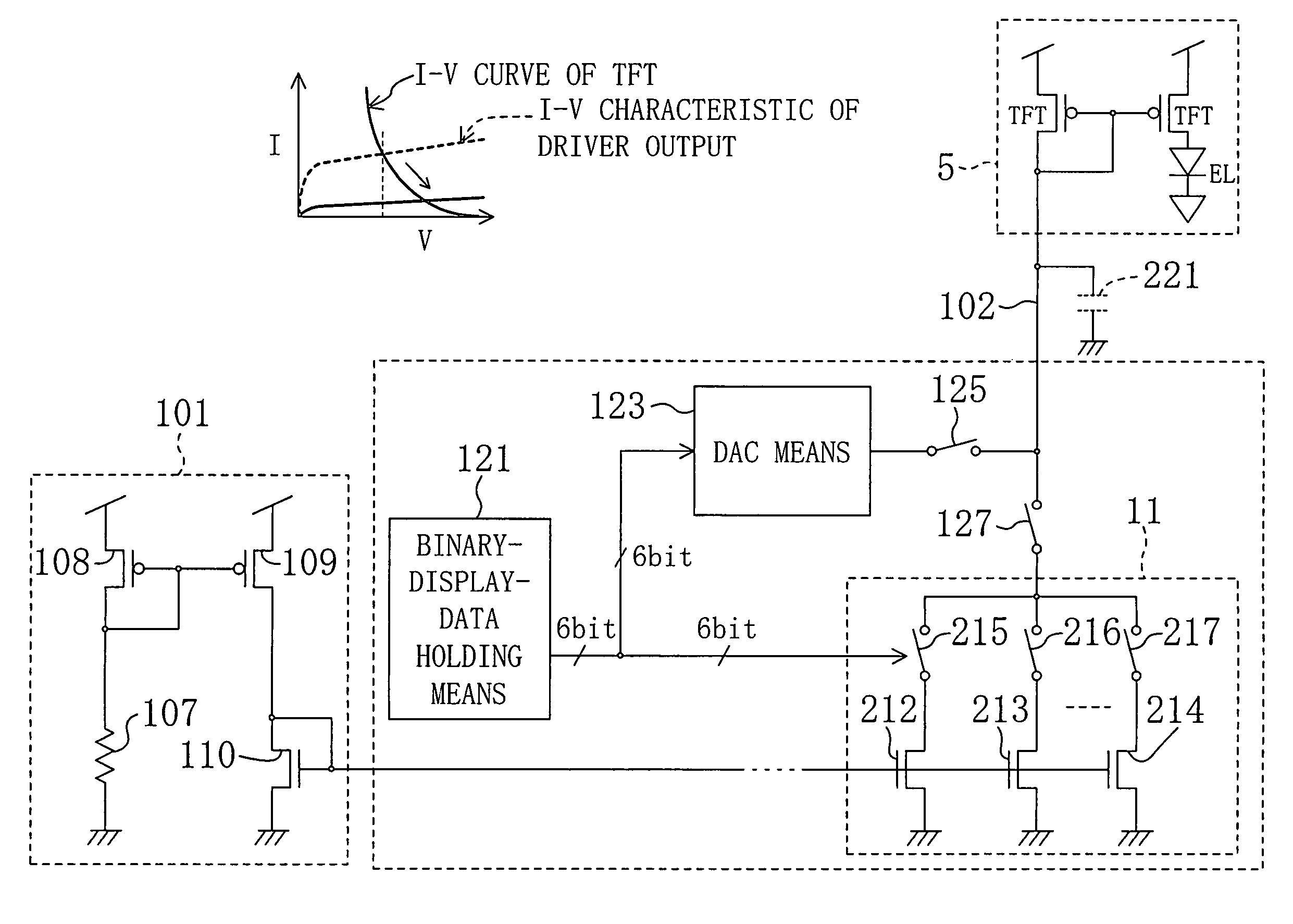
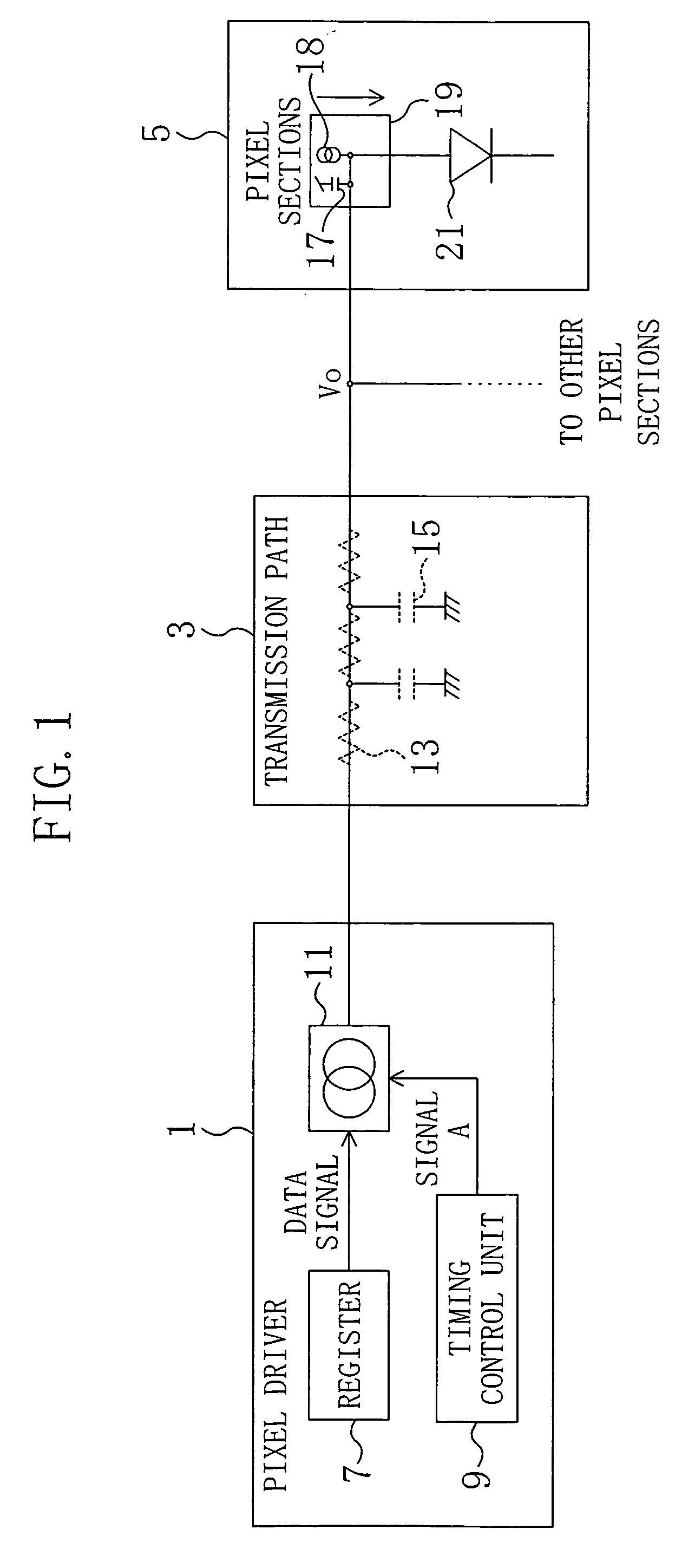
[0103]FIG. 1 is a circuit block diagram schematically showing a configuration of an organic EL display apparatus according to a first embodiment of the present invention. The organic EL display apparatus of this embodiment is characterized in that a predetermined amount of current flows from a pixel driver 1 for a given period in a current setting mode, and then the value of the current that has been set is output from the pixel driver 1.

[0104]As shown in FIG. 1, the organic EL display apparatus of this embodiment includes: a display panel; a pixel section 5 provided on the display panel and used for displaying an image; a transmission path 3 connected to the pixel section 5; and a pixel driver 1 included in a source driver and used for supplying a drive current to the pixel section 5 via the transmission path 3. The transmission path 3 includes a line connecting the source driver 1 and the display panel to each other and a signal line provided on the display panel. The transmission...

first specific example

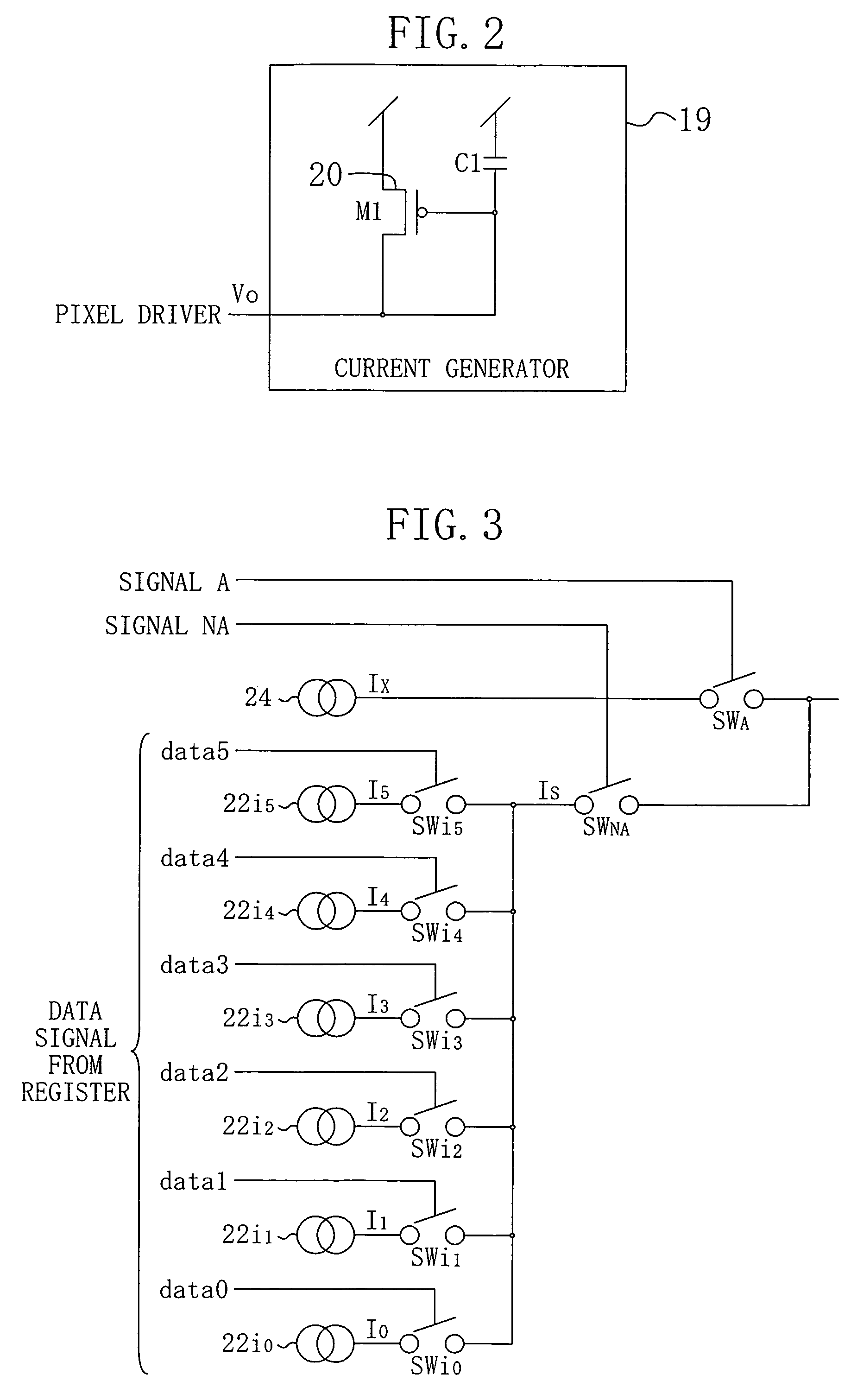
[0111]FIG. 3 is a circuit diagram showing a first specific example of the current driver of the organic EL display apparatus of the first embodiment. In this example, the organic EL display apparatus produces a display of 6 bits, i.e., 64 levels of gray scale.

[0112]The current driver of this specific example shown in FIG. 3 includes: an additional current source 24 for supplying a constant current Ix; a current mode D / A converter for receiving a data signal output from the register 7 and outputting a current according to the data signal; a switch SWA for switching between ON and OFF of the current flowing in the additional current source 24; and a switch SWNA for switching between ON and OFF of an output current (drawn current) of the current mode D / A converter. The switch SWA is controlled with the signal A, and the switch SWNA is controlled with a signal NA, which is a signal of opposite phase to that of the first control signal A.

[0113]The current mode D / A converter includes: a f...

second specific example

[0122]FIG. 5 is a circuit diagram showing a second specific example of the current driver in the organic EL display apparatus of the first embodiment. In this specific example, no additional current source is provided, and the current driver allows the maximum output current to flow using the first through sixth current sources of the current mode D / A converter only during a given period in the current setting mode.

[0123]As shown in FIG. 5, the current driver of this specific example includes: a D / A converter having the same configuration as in the first specific example: bypasses respectively connecting the first through sixth current sources to an output terminal of the D / A converter; a switch SWA0 provided between the first current source 22i0 and the output terminal of the D / A converter; a switch SWA1 provided between the second current source 22i1 and the output terminal of the D / A converter; a switch SWA2 provided between the third current source 22i2 and the output terminal o...


PUM


Abstract

An organic EL display apparatus includes: a display panel on which a plurality of pixel sections are provided; source drivers provided with pixel drivers, which includes current drivers for supplying drive currents to the pixel sections, registers for latching data signals and timing control units; signal lines for supplying the drive currents from the current drivers to the pixel sections. Each of the current drivers is controlled by the associated timing control unit to allow a current larger than or equal to a current which is set in accordance with the data signal to flow only during a given period in a current setting mode, so that the value of a current flowing in the pixel section reaches a target value in a short time.

Description

[0001]This nonprovisional application claims priority under 35 U.S.C. §119(a) on Japanese Patent Application No. 2003-105694, the entire contents of which are hereby incorporated by reference.BACKGROUND OF THE INVENTION[0002]The present invention relates to a display apparatus including a light-emitting device driven by current such as an organic electro luminescence (EL) device, to a source driver used in the display apparatus, and to a display panel.[0003]In an active matrix type image display apparatus, a large number of pixels are arranged in a matrix pattern and the intensity of light is controlled for every pixel depending on provided luminance information, thereby displaying an image. For this purpose, a rectangular display panel, for example, includes thin-film-transistors (TFTs) arranged in a matrix pattern and controlling the state of liquid crystal or an optical material, source drivers provided along the upper and lower sides of the panel and gate drivers provided at the...

Claims


Application Information

Patent Timeline
IPC IPC(8): G09G3/32G09G3/30G09G5/10H01L51/50G09G3/20
CPCG09G3/325G09G3/3283G09G3/3291G09G3/3241G09G2320/0252G09G2310/0248G09G2310/0251G09G2310/027G09G2320/0223G09G2300/0842G09G3/30
Inventor OOMORI, TETSUROUDATE, YOSHITO
Owner COLLABO INNOVATIONS INC
Why Eureka
Try Eureka