Cooled turbine airfoils and methods of manufacture

a technology of cooling turbine and airfoil, which is applied in the field of investment casting, can solve the problems of difficult manufacturing, limited hole shape produced by such edm techniques, and associated cost of engine efficiency

Active Publication Date: 2007-12-11
RTX CORP
View PDF13 Cites 59 Cited by
  • Summary
  • Abstract
  • Description
  • Claims
  • Application Information

AI Technical Summary

Problems solved by technology

Such cooling comes with an associated cost in engine efficiency.
The cores defining fine features may be difficult to manufacture and / or, once manufactured, may prove fragile.
The hole shapes produced by such EDM techniques are limited by electrode insertion constraints.
As is the case with the use of multiple ceramic cores, assembling the ceramic and refractory metal cores and maintaining their spatial relationship during wax overmolding presents numerous difficulties.
A failure to maintain such relationship can produce potentially unsatisfactory part internal features.
It may be difficult to assemble fine refractory metal cores to ceramic cores.
Once assembled, it may be difficult to maintain alignment.
The refractory metal cores may become damaged during handling or during assembly of the overmolding die.
Assuring proper die assembly and release of the injected pattern may require die complexity (e.g., a large number of separate die parts and separate pull directions to accommodate the various RMCs).

Method used


Image

  • Cooled turbine airfoils and methods of manufacture
  • Cooled turbine airfoils and methods of manufacture
  • Cooled turbine airfoils and methods of manufacture

Examples


Embodiment Construction

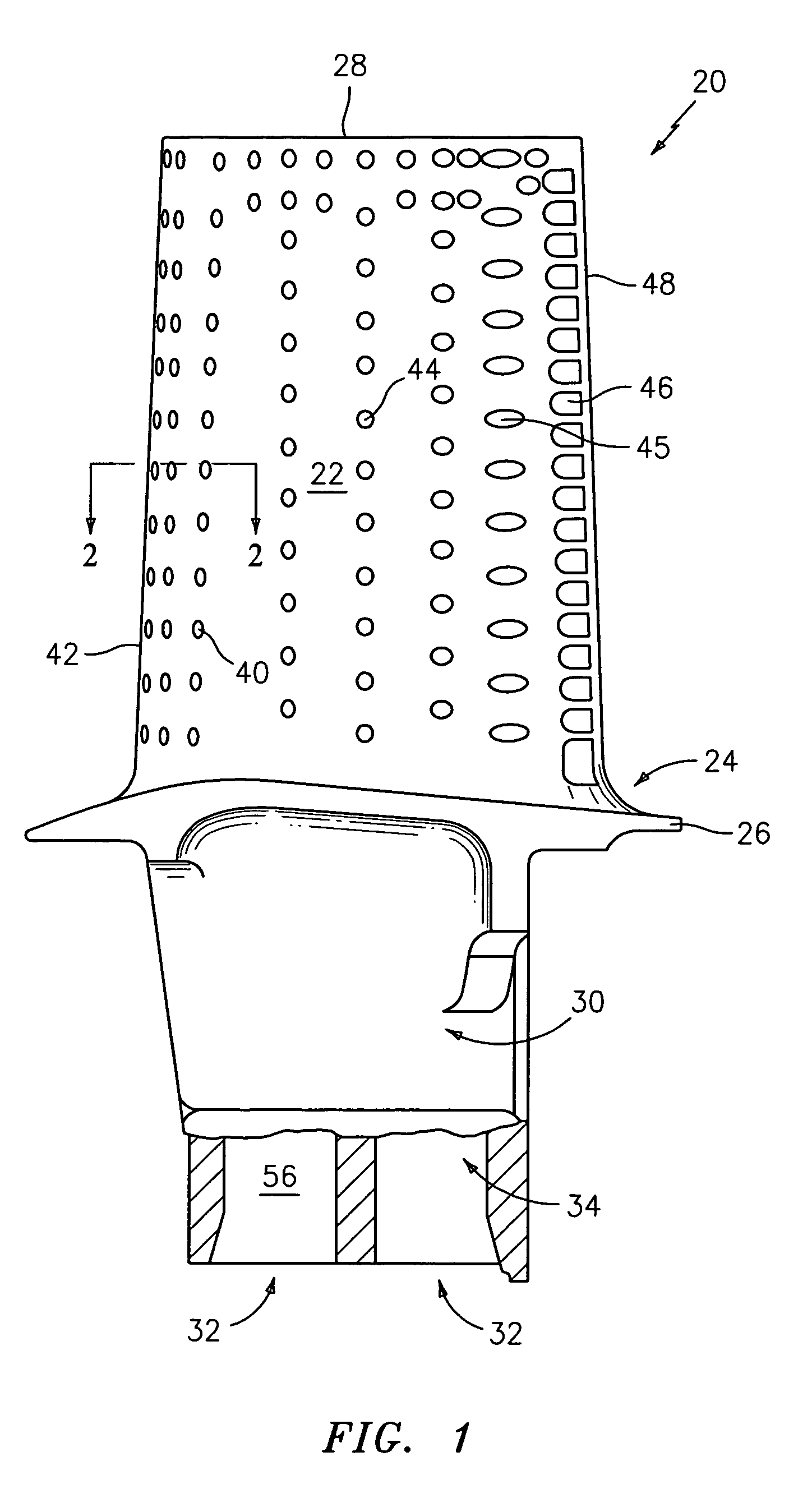
[0026]FIG. 1 shows an exemplary turbine element in the form of a blade 20. The blade has an airfoil 22 extending from a root 24 at a platform 26 to a tip 28. A blade attachment root 30 depends from the platform 26 and includes an exemplary pair of inlet ports 32 to a cooling passageway network 34 within the blade. The network 34 extends to a number of outlets located on the surface of the airfoil. Exemplary outlets include arrays of outlets 40 near an airfoil leading edge 42. Additional outlets 44, 45, and 46 are arrayed downstream toward the trailing edge 48.

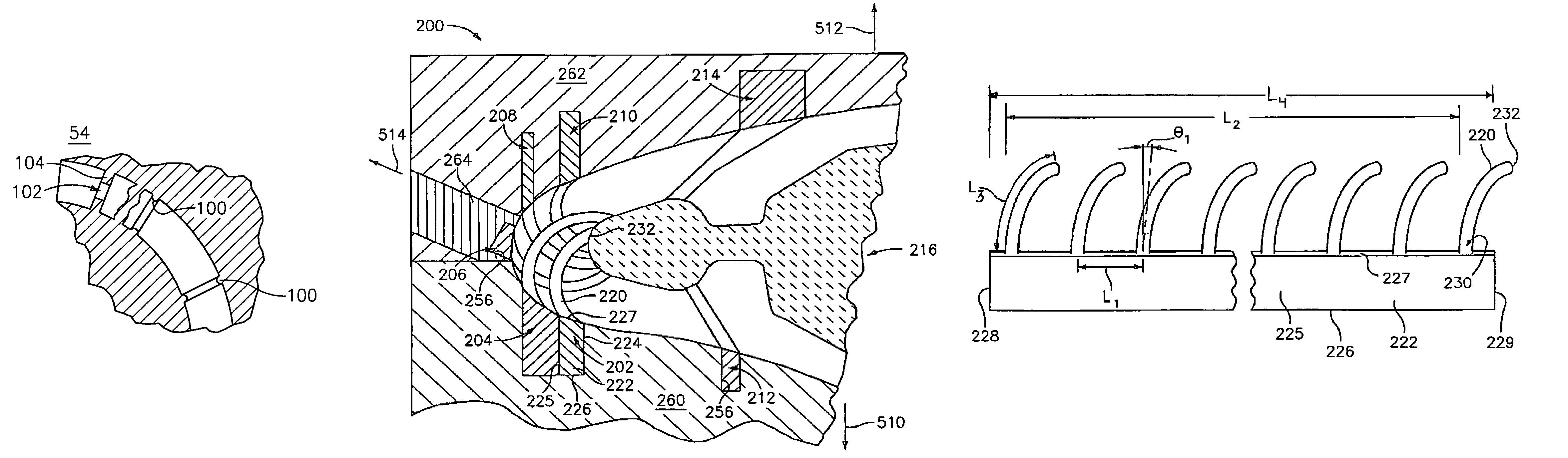
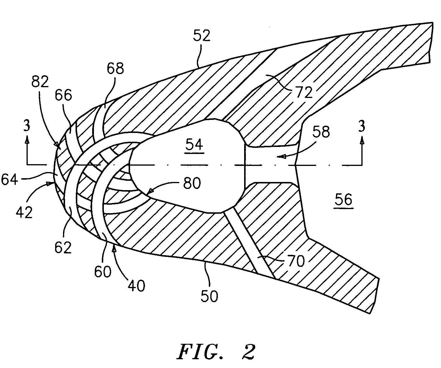
[0027]FIG. 2 shows the airfoil 22 as including pressure and suction side surfaces 50 and 52. FIG. 2 further shows a leading leg 54 of the passageway network and a second leg 56. In the exemplary airflow, the second leg 56 feeds cooling air to the leading leg 54 via connecting impingement passageways 58. The leading leg 54 (an impingement cavity), in turn, feeds a number of discharge / outlet passageways 60, 62, 64, 66, 68, 70, an...


PUM


Abstract

An investment casting pattern is formed by installing a first core to a first element of a molding die to leave a first portion of the first core protruding from the first element. After the installing, the first element is assembled with a feed core and a second element of the molding die so that the first portion contacts the feed core. A material is molded at least partially over the first core and the feed core. The first portion has one or more surface area enhancements.

Description

BACKGROUND OF THE INVENTION[0001]The invention relates to investment casting. More particularly, the invention relates to casting of film cooling holes in gas turbine engine components.[0002]Investment casting is a commonly used technique for forming metallic components having complex geometries, especially hollow components, and is used in the fabrication of superalloy gas turbine engine components.[0003]Gas turbine engines are widely used in aircraft propulsion, electric power generation, ship propulsion, and pumps. In gas turbine engine applications, efficiency is a prime objective. Improved gas turbine engine efficiency can be obtained by operating at higher temperatures, however current operating temperatures in the turbine section exceed the melting points of the superalloy materials used in turbine components. Consequently, it is a general practice to provide air cooling. Cooling is typically provided by flowing relatively cool air from the compressor section of the engine th...

Claims


Application Information

Patent Timeline
Patent Type & Authority Patents(United States)
IPC IPC(8): B22C9/04B22C9/10
CPCB22C7/02B22C9/04B22C9/103B22C21/14F01D5/147F01D5/187F01D5/182F05D2260/202Y02T50/672Y02T50/676F05D2230/211F05D2250/25Y02T50/60B22C9/10
Inventor MEMMEN, ROBERT L.
Owner RTX CORP
Why Eureka
Try Eureka