
Sheet conveying apparatus and image forming apparatus

a technology of conveying apparatus and sheet, applied in the direction of registering device, thin material processing, article separation, etc., can solve the problems of difficult to achieve an improvement in productivity, difficult to perform the alignment itself, and naturally distorted image with respect to the sh

Active Publication Date: 2007-12-11
CANON KK
View PDF10 Cites 23 Cited by
  • Summary
  • Abstract
  • Description
  • Claims
  • Application Information

AI Technical Summary

Benefits of technology

The present invention provides a sheet conveying apparatus for an image forming apparatus that can correct skew feed of a sheet conveyed using a sheet center as a reference. The apparatus includes a skew feed correcting device with a first conveying guide, an aligning means, a contact-separation means, a second conveying guide, a positioning means, a second rotary roller pair, a slide means, and a sheet detecting means. The apparatus can align the sheet and correct skew feed by moving the first conveying guide and the second rotary roller pair based on detection of the sheet by the sheet detecting means. The technical effect of the invention is to improve the accuracy of sheet conveyance and image formation.

Problems solved by technology

If image formation is conducted with skew feed neglected, the resultant image is naturally distorted with respect to the sheet.
First, the problem in the registration-roller-type skew feed correcting device will be discussed. This skew feed correcting device, which corrects skew feed by using the sheet leading edge as a reference, is capable of correcting skew feed of the trailing edge of a sheet, but is incapable of correcting deviation in the sheet width direction (the direction orthogonal to the conveying direction). Further, since the sheet is caused to abut the registration roller pair, it is necessary to effect temporary stopping, which makes it difficult to achieve an improvement in productivity. Further, when effecting correction on a thick-fore-edge sheet, such as the cover of a booklet, it may occur that a loop cannot be formed due to the high rigidity of the sheet. Further, in some cases, the sheet may penetrate the nip of the registration rollers, thus making it impossible to perform the alignment itself. Further, in an image forming apparatus with a two-side printing function, when effecting switch-back reversal on the sheet, the leading edge of the first surface is replaced by that of the second surface, so that a deviation in parallelism between the leading and trailing edges of the sheet manifests itself as an image deviation.
A high holding pressure results in an increase in conveying speed, which leads to skew feed.
Further, due to the irregularity in holding pressure, the roller undergoes uneven wear, which is also liable to cause skew feed in the conveying path.
In particular, when the uneven wear progresses as a result of long-term use, it is to be expected that, sooner or later, the skew feed amount will increase beyond the permissible amount for the skew feed correcting device.
On the other hand, provision of a pressure adjustment mechanism for making the holding pressure in the width direction of the conveying roller uniform would complicate the device construction and adjusting operation and lead to an increase in production cost, which is not desirable.

Method used


Image

  • Sheet conveying apparatus and image forming apparatus
  • Sheet conveying apparatus and image forming apparatus
  • Sheet conveying apparatus and image forming apparatus

Examples


Embodiment Construction

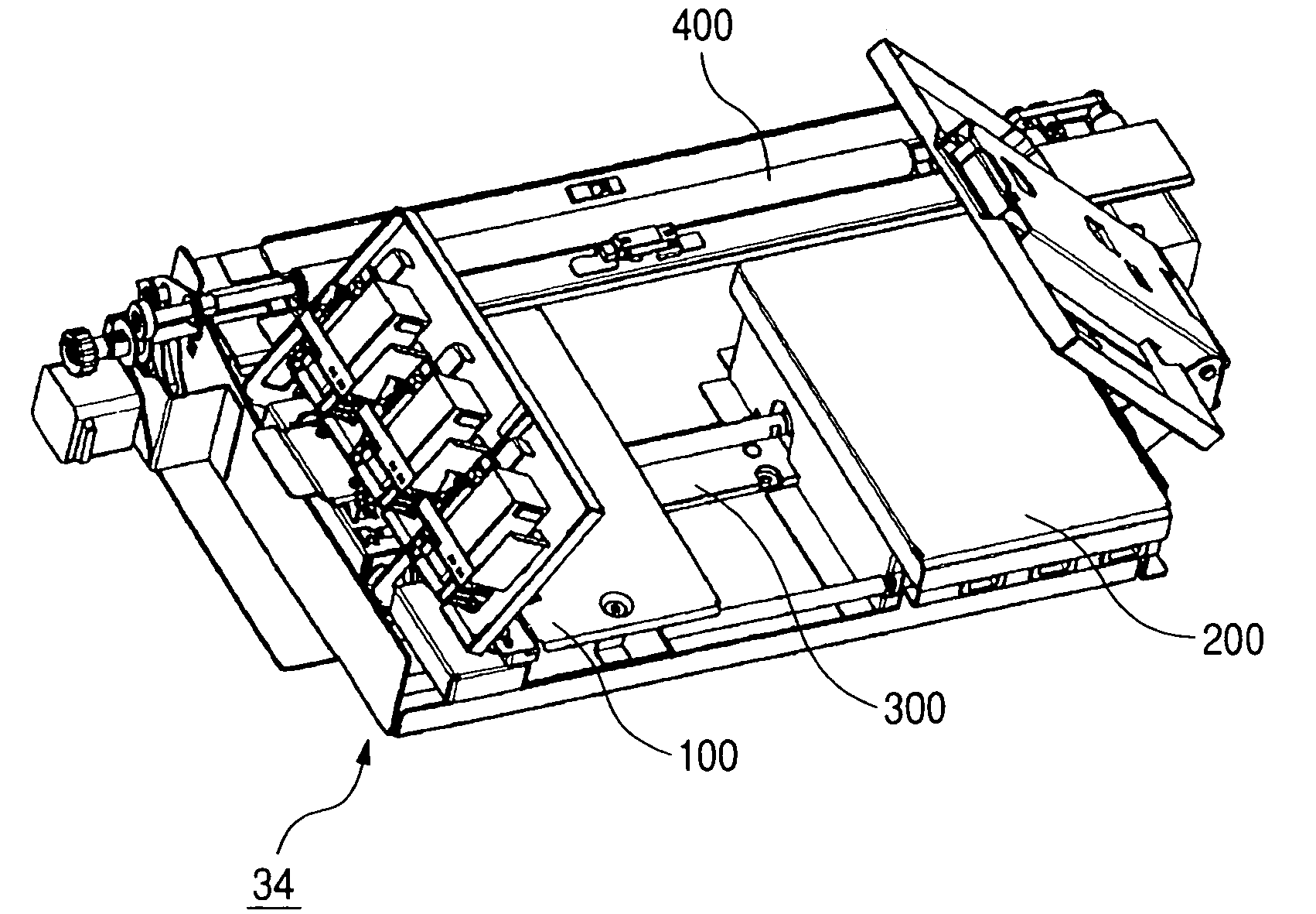
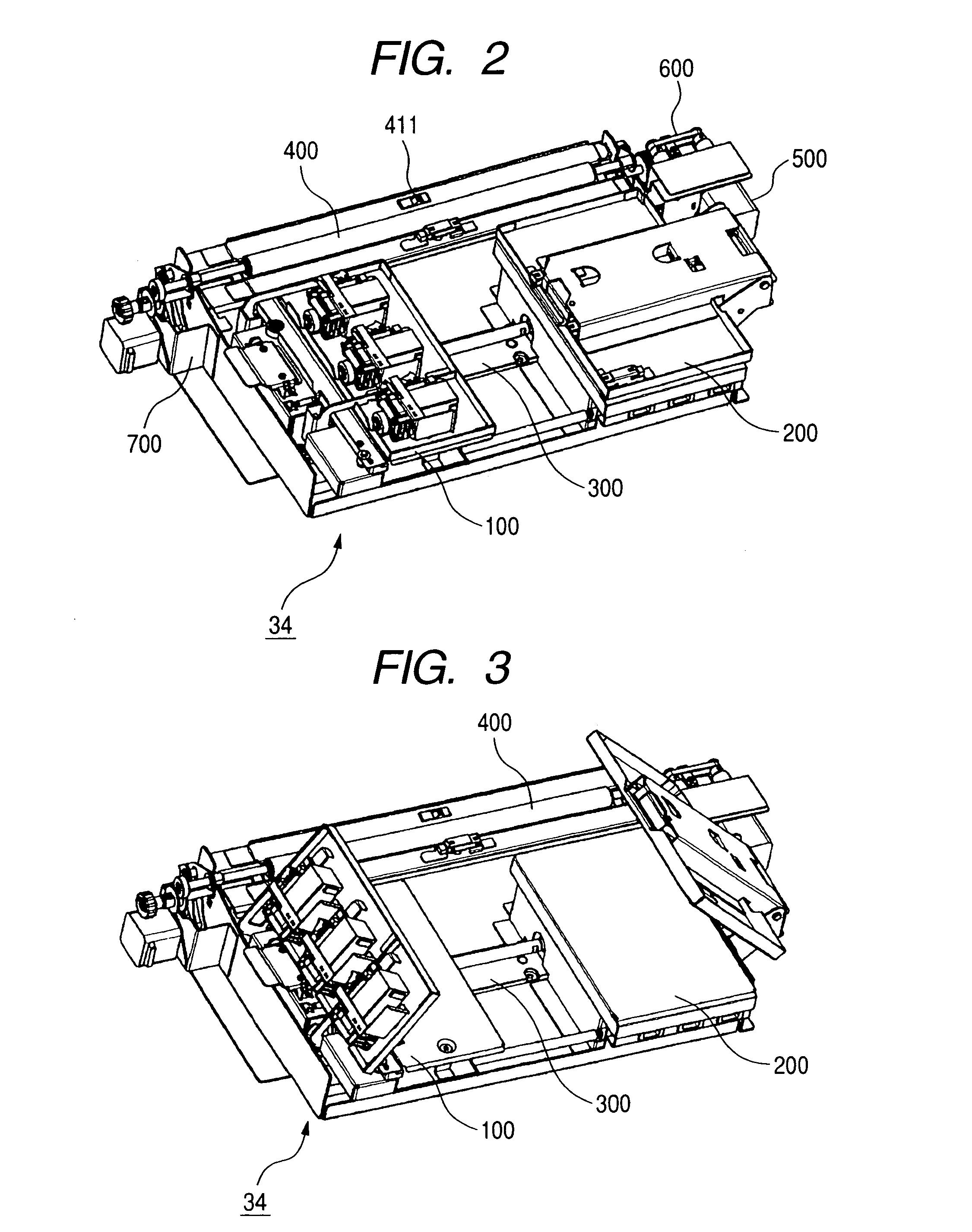
[0039]A skew feed correcting device according to the present invention and an image forming apparatus equipped with the same will be described by way of example. The description will be given in the following order: the general construction of the image forming apparatus, the construction of the skew feed correcting device, and the characteristic operation of this embodiment.

{General Construction of the Image Forming Apparatus}

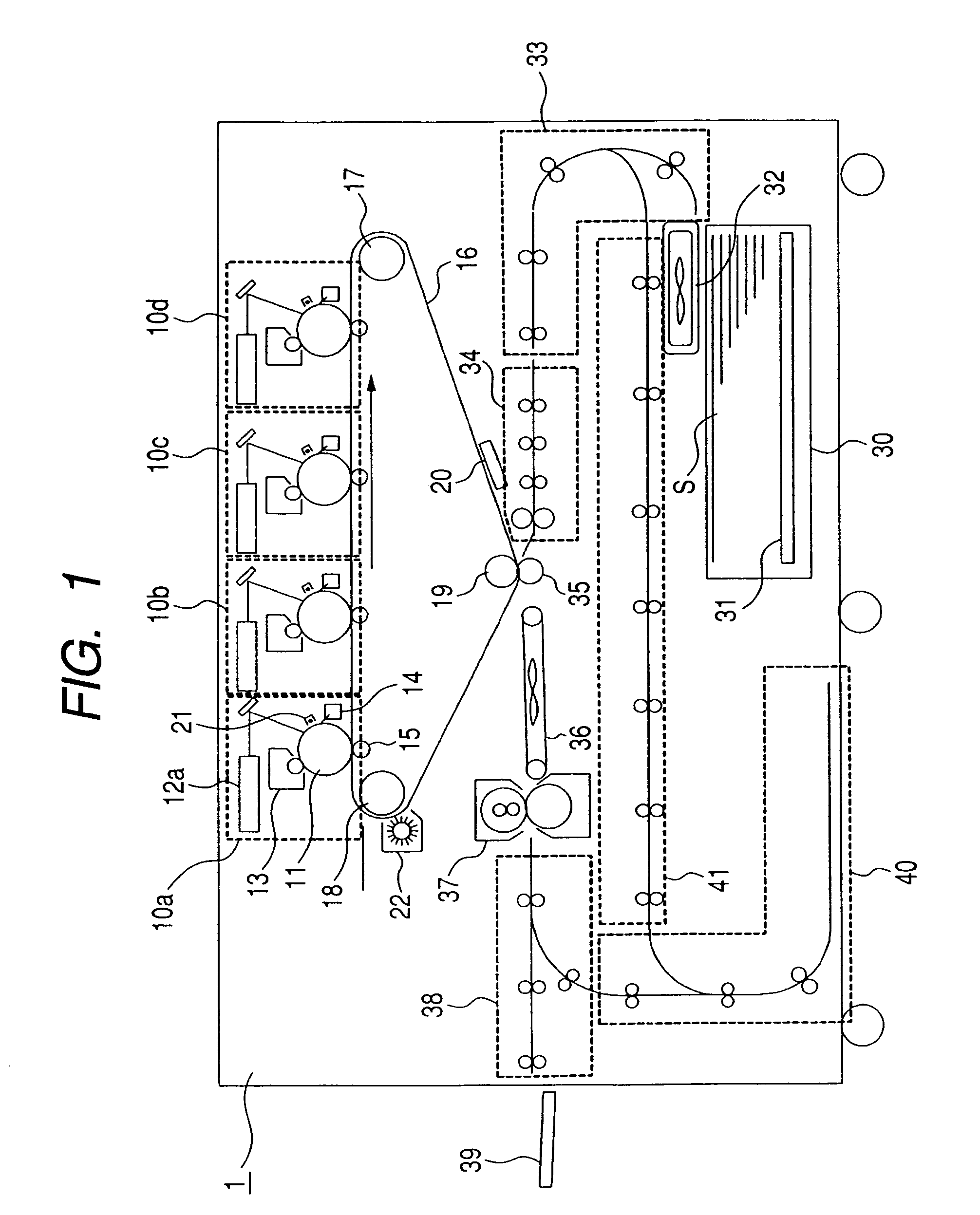
[0040]The general construction of the image forming apparatus will be described with reference to FIG. 1. FIG. 1 is a sectional view schematically showing the construction of the image forming apparatus of this embodiment.

[0041]FIG. 1 shows an image forming apparatus 1 that consists of a color printer using an electrophotographic process, which is equipped with a registration portion 34 described below as an example of the skew feed correcting device. In the image forming apparatus 1, image forming portions 10a through 10d for forming images of the colors of y...


PUM


Abstract

A sheet conveying apparatus with a skew feed correcting device including a first guide supporting one side edge of the sheet, an aligning device provided in the first guide and having an abutment portion and a first roller pair for causing the sheet to abut the abutment portion, a contact-separation device for separating and contacting the first roller pair, a second guide supporting the other side edge of the sheet, a positioning device for moving the first guide in a direction substantially perpendicular to a sheet conveying direction, a second roller pair downstream of the first and second guides, a slide device for moving the second roller pair in the direction, and a sheet detector. When conveying the sheet, the positioning device moves the first guide such that the abutment portion is at a predetermined distance from the side edge of the sheet, the sheet is conveyed while aligned by abutted against the abutment portion by the first roller pair, the first roller pair is separated by the contact-separation device based on the detection of the sheet detector, and the sheet is moved by the slide device so as to be returned by the predetermined distance while held by the second roller pair.

Description

BACKGROUND OF THE INVENTION[0001]1. Field of the Invention[0002]The present invention relates to an image forming apparatus, such as a printer or a copying machine, and, in particular, to a sheet conveying apparatus equipped with a skew feed correcting device for correcting skew feed of a sheet.[0003]2. Related Background Art[0004]Generally, an image forming apparatus, such as a printer or a copying machine, is equipped with a sheet conveying apparatus for conveying a sheet as a transfer material. In the sheet conveying apparatus, a phenomenon called skew feed may occur during conveyance due to misalignment of the conveying roller, distortion of a sheet guide, etc. that are attributable to inadequacy in the assembly precision of the components. If image formation is conducted with skew feed neglected, the resultant image is naturally distorted with respect to the sheet. In particular, in an image forming apparatus with a two-side printing function, there may be involved a marked dev...

Claims


Application Information

Patent Timeline
Patent Type & Authority Patents(United States)
IPC IPC(8): B65H9/16B65H9/00B65H5/00B65H5/06B65H9/04B65H9/10
CPCB65H5/062B65H9/166B65H9/04B65H2404/1442
Inventor AGATA, JUN
Owner CANON KK
Learn More