Seating apparatus with tilted surface and the chair with the same

a technology of tilting surface and seat, which is applied in the direction of chairs, movable seats, wheelchairs/patient conveyances, etc., can solve the problems of inability to apply, unfavorable work performance, and high cost, so as to prevent the break out of lower back pain, reduce the stress around the spine and lower back, and reduce the effect of back pain

Inactive Publication Date: 2007-12-11
KOBAYASHI TOMIO
View PDF14 Cites 12 Cited by
  • Summary
  • Abstract
  • Description
  • Claims
  • Application Information

AI Technical Summary

Benefits of technology

[0032]The important advantage of the present invention is that the sitting with less stress around spine and lower back can be obtained by setting this invented seating apparatus on the fundamentally horizontal sitting base plate of the office chair. The use of this seating apparatus contributes to prevent the break out of the lower back pain and make the person with lower back pain feel it less than the sitting without this apparatus.
[0033]Another advantage of the present invention is the steady sitting situation actualized by stopping the body to slip down the seating base plate, which is given by the new structure with at least the seating base plate, the knee front holder and the supporting part. The comfortable support is actualized through the knee front holder.
[0034]Still another advantage of the present invention is that the concept of the invention can be applied on the chair itself from the beginning. The installation of the composition of the seating apparatus into the chair enables to enlarge the angle between the spine and the thigh from 95 to 135 degrees and to sit with less stress around the lower back.
[0035]Some detailed examples of the present invention to actualize in best way are explained here. The first one of the three essential composing elements of the present invention is the seating base plate, which is tilted forward down and the hips are set on. This plate has the feature that the angle between the seating base plate and the seating bottom plate is ranged from 5 to 45 degrees and this construction enables the situation to keep the seating base plate as tilted 5 to 45 degrees against the horizontal plane, when the seating apparatus is set on the horizontal sitting plate of the chair.
[0036]Concerning about the angle between the seating base plate and the bottom plate, it is suitable to keep over 5 degrees because of the effectiveness of preventing lower back pain. It is much more suitable to keep over 10 degrees for higher effectiveness against long hours sitting.
[0037]On the other hand, the larger angle than 45 degrees is not suitable, because the too much weight is loaded against the knee front holder, as the reaction, and against the knee front itself. For getting the moderate weight balance to the knee and the hips, and also the comfortable posture for the long hours sitting, the smaller angle than the 45 degrees is selected.

Problems solved by technology

However, the chair with the knee supporting plane to prevent the person sliding down on the seating plane, which is called as sit knee chair, is un-convenient to perform the work by sitting in front of the desk for the person who don't feel a lower back pain.
And, the chair with automatic tilting or moving mechanism of the sitting plane, shown in the Japanese Patent of Number 3,106,360 or 2,524,462, has the problem of the expensive cost and the bigger size compared to the ordinary office chair.
But, the larger angle as like as the case of sit knee chair cannot be applied because of that the hips slip down the seating surface to un-steady sitting.

Method used


Image

  • Seating apparatus with tilted surface and the chair with the same
  • Seating apparatus with tilted surface and the chair with the same
  • Seating apparatus with tilted surface and the chair with the same

Examples


first example

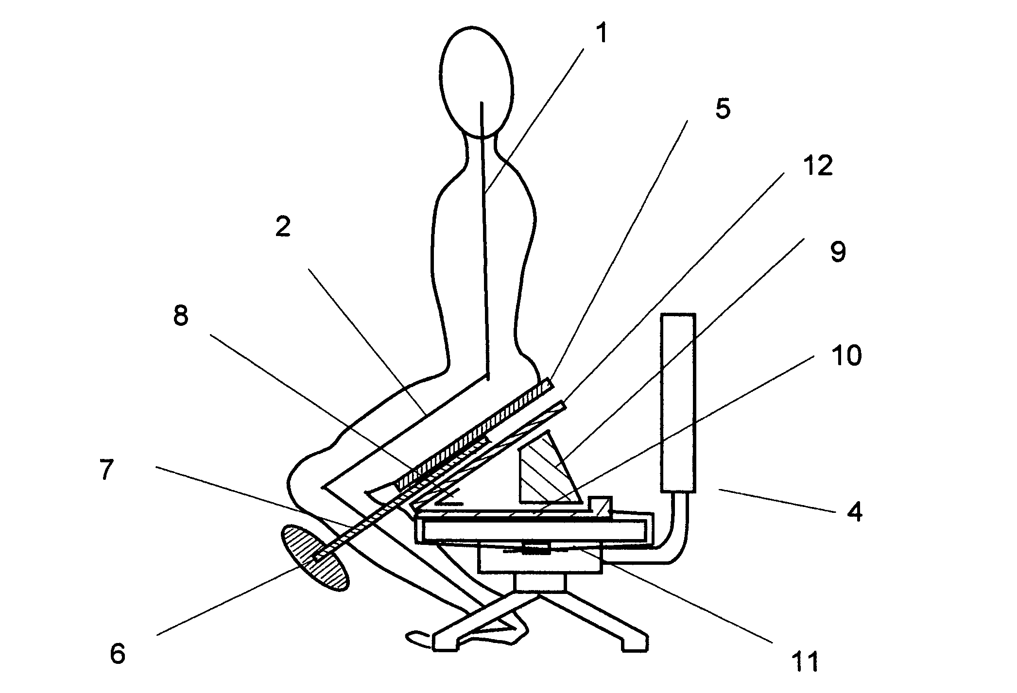
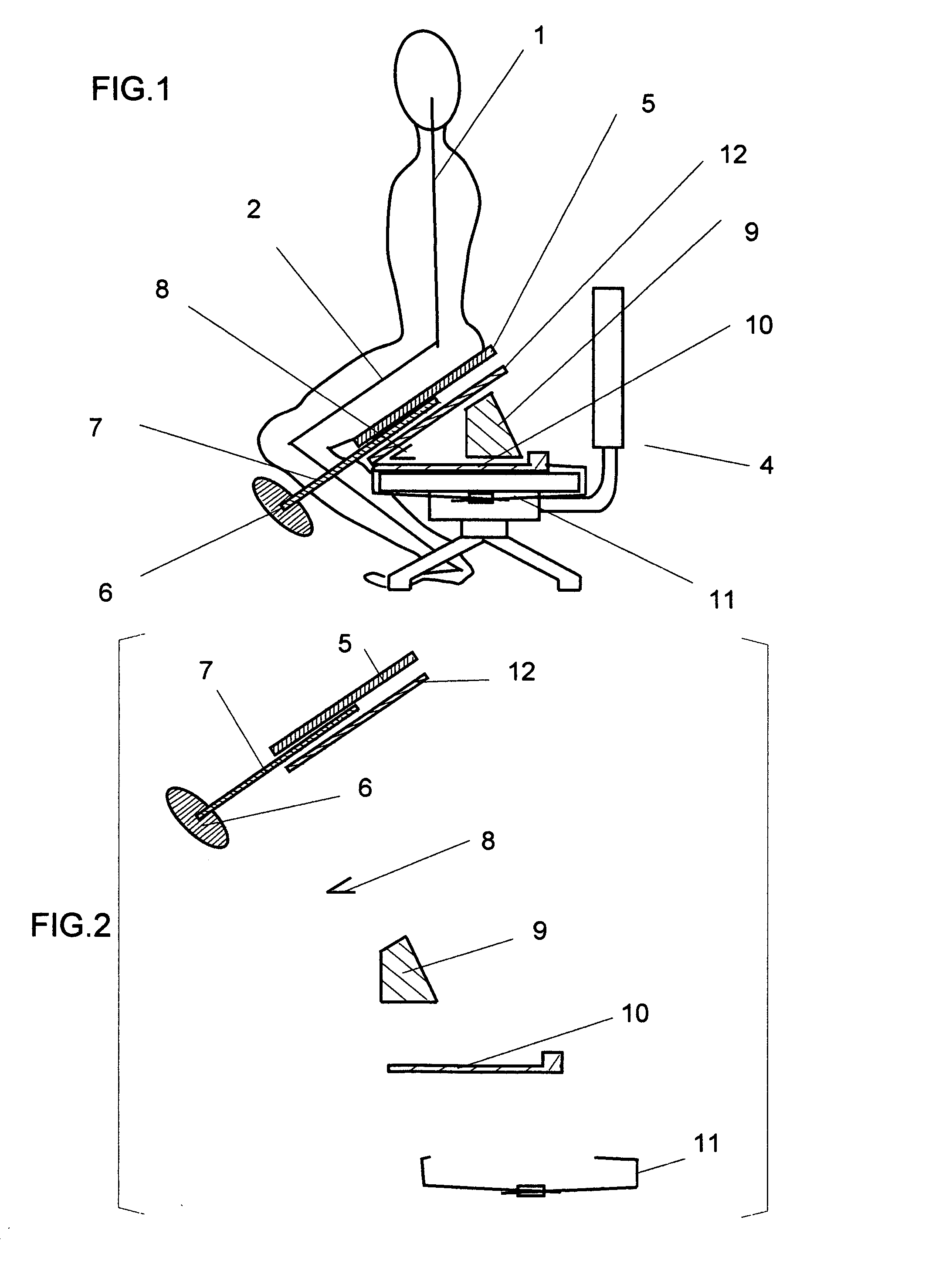
[0086]FIG. 1 is a schematic sectional view illustrating the posture of the person sitting on the office chair 4 with the seating apparatus of the present invention. As the FIG. 1 is illustrated schematically to be able to understand the entire relation among the related parts, the sections of the various parts at the individual peculiar section plane are shown and arranged together without showing one common section at an absolute common plane.

[0087]In FIG. 1, a seating apparatus by the present invention is composed of the seating base plate 5, the knee front holder 6, the supporting part 7, the hinge 8, the slanted block 9, the seating bottom plate 10, the fixing belt 11 and the seating back plate 12. And as explained precisely later, the seating base plate 5 is situated parallel to the seating back plate 12 and kept away some distance. The knee front holder 6 is connected with the supporting part 7, and another end portion of the supporting part 7 opposite from the knee front hold...

second example

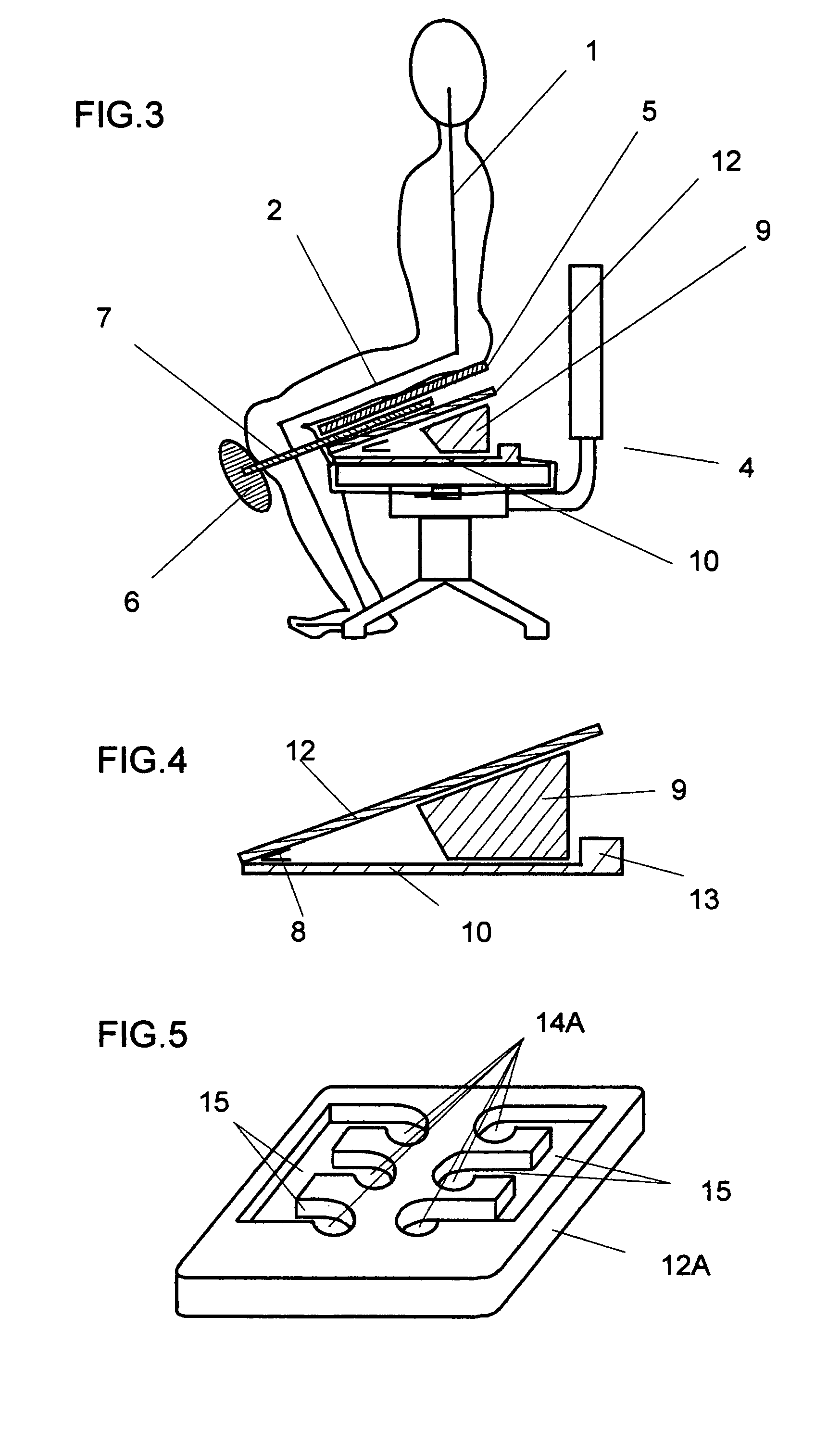
[0098]Next, the second example is explained by using FIG. 12 to 15. The hollow portion 14B of the hollow and projection engagement is formed in the seating plate spacer 16B itself in FIG. 12. As shown in the FIG. 13, the knee front holder 6B and the projecting portion 17B are formed on each end of the supporting part 7B. And as shown in FIG. 14, the seating plate spacer 16B is sandwiched between the seating base plate 5B and the seating back plate 12B. As the seating base plate 5B and the seating back plate 12B have the planer surfaces, the projecting portion 17B of the supporting part can be moved in the space formed by the seating plate spacer 16B.

[0099]Concerning about the thickness example of the each planar plate, the supporting part 7B is formed by hollowing out the shape of the FIG. 13 from the 9 mm thickness board, and the seating plate spacer 16B is formed from the 10 mm thickness board. The seating base plate 5B and the seating back plate 12B are made of the 6 mm thickness...

third example

[0103]Next, the relation between the seating base plate and the supporting part in the third example of the present invention is shown in the FIG. 16 to 17. The hole 20 is situated at the side surface of the seating base plate 5C, and the hook portion 21C is situated on the opposite end portion from the knee front holder 6C in the supporting part 7C. In the third example, the back surface of the seating base plate 5C is faced directly to the seating bottom plate 10, and the seating base plate 5C is connected with the seating bottom plate 10 at the front tip position by the hinge 8. The load onto the knee front holder 6C is transferred to the seating base plate 5C by inserting the hook portion 21C into the hole 20.

[0104]Another structure of the hook portion 21C is shown in the FIG. 17, which is jointed with the supporting part 7C by the screw hole 22 with the bolt 23 and the nut 24. By using this method of joint, the load transfer by the supporting part 7C is possible on the same tim...


PUM


Abstract

The invention provide the seating apparatus to be used on the chair of the horizontal sitting base plate in order to avoid the lower back pain. By sitting on the seating base plate tilted forward from 5 to 45 degree, the person can keep the angle between the spine and the thigh from 95 to 135 degree. As the seating apparatus is equipped with the knee front holder connected with the supporting part, which is connected with the seating base plate by the half fixed joint at an another end of the supporting part, the slip down of the body on the seating base plate is stopped by the knee front holder and the steady sitting is available.

Description

BACKGROUND OF THE INVENTION[0001]1. Field of the Invention[0002]The present invention relates to a seating apparatus used on the chair and to the chair with the said seating apparatus structure.[0003]2. Description of Related Art[0004]The sitting plane of the chair is usually situated parallel to horizontal plane as shown in FIG. 35. FIG. 35 is the schematic diagram of the chair with the person who sits on it. Though the sitting plane of the relaxing use chair is slanted to the backward lower and the chair back is declined backward to be able to sit lying on his back, the office chair used in front of the office desk has the horizontal sitting base plate in order to look at the documents straight.[0005]As the sitting base plate of the chair is situated almost parallel to the horizontal plane, the angle between the spine 1 and the thigh 2 of the sitting person is smaller than about 100 degrees and almost near to 90 degrees in usual case as seen in FIG. 35.[0006]When we sit long hours...

Claims


Application Information

Patent Timeline
Patent Type & Authority Patents(United States)
IPC IPC(8): A47C7/50A47C16/00A47C27/04A47C9/00A47C27/00A61F5/01A61G5/00
CPCA47C9/005A47C7/503
Inventor KOBAYASHI, TOMIO
Owner KOBAYASHI TOMIO
Why Eureka
Try Eureka