
Methods for providing a reliable server architecture using a multicast topology in a communications network

a multicast topology and communication network technology, applied in the field of communication networks, can solve the problems of inefficient approach in message traffic inability to provide reliable server architecture, etc., and achieve the effect of greater reliability of algorithmic services

Active Publication Date: 2007-12-11
RPX CORP +1
View PDF6 Cites 17 Cited by
  • Summary
  • Abstract
  • Description
  • Claims
  • Application Information

AI Technical Summary

Benefits of technology

[0006]The present invention provides a reliable server architecture using a multicast topology established between host computer elements and servers of a communication network, in a manner that does not require the hosts to be aware of which of multiple redundant servers is active and which reduces message traffic relative to the prior art. In the preferred embodiment, the servers provide a gateway function and the server architecture is used to provide fault-tolerant transmission paths between the hosts and an external network. More generally, the servers perform an algorithmic service to requesting programs on host computers and the server architecture is used to provide greater reliability of the algorithmic service.

Problems solved by technology

However, this approach is inefficient in terms of message traffic and can cause intolerable delays due to the time required for the network to detect failure of the active server, identify the backup server as the newly active server and inform the hosts accordingly.
However, this approach is even less efficient and may cause adverse effects (e.g., quality, bandwidth) on the network due to superfluous message traffic.

Method used


Image

  • Methods for providing a reliable server architecture using a multicast topology in a communications network
  • Methods for providing a reliable server architecture using a multicast topology in a communications network
  • Methods for providing a reliable server architecture using a multicast topology in a communications network

Examples


Embodiment Construction

)

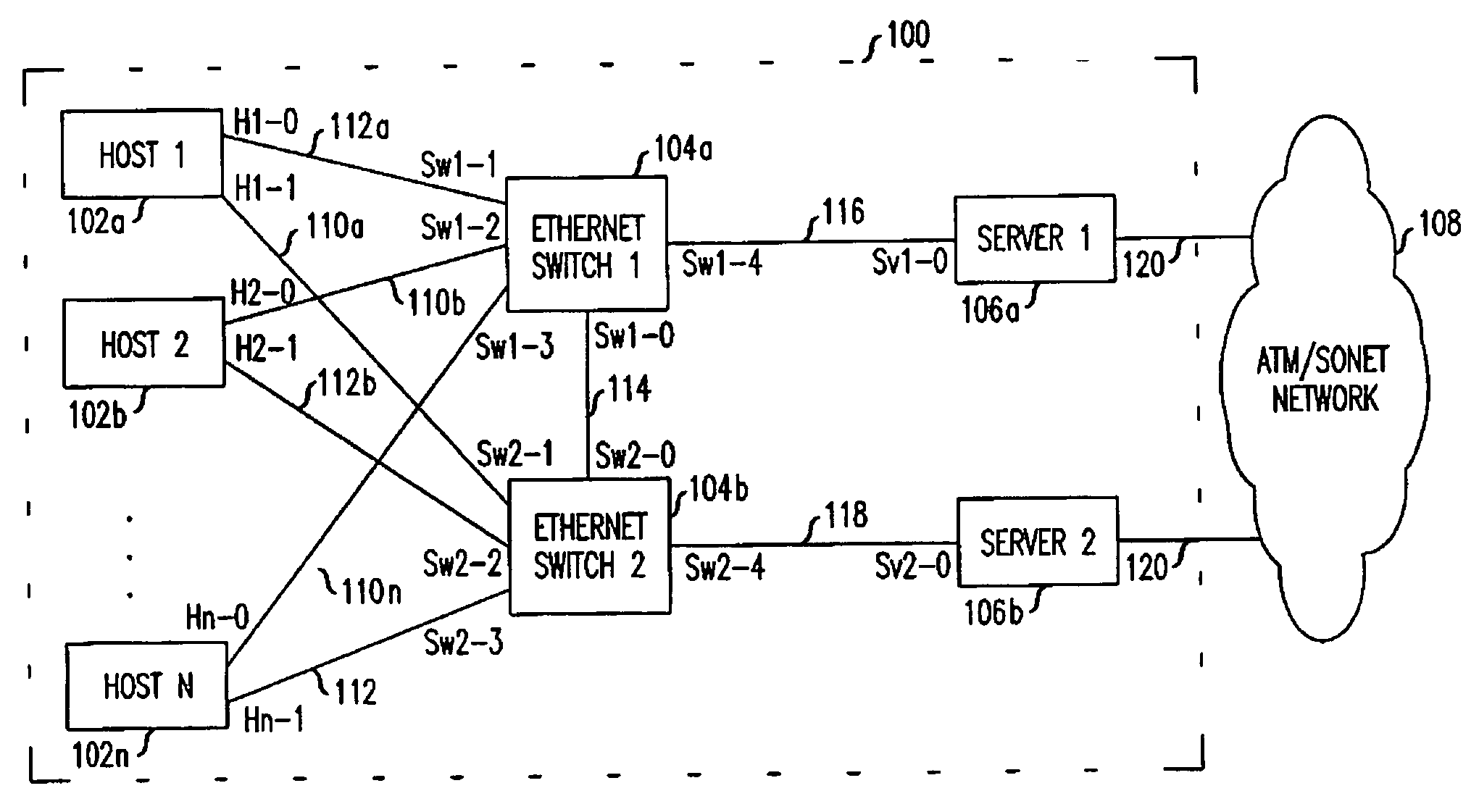
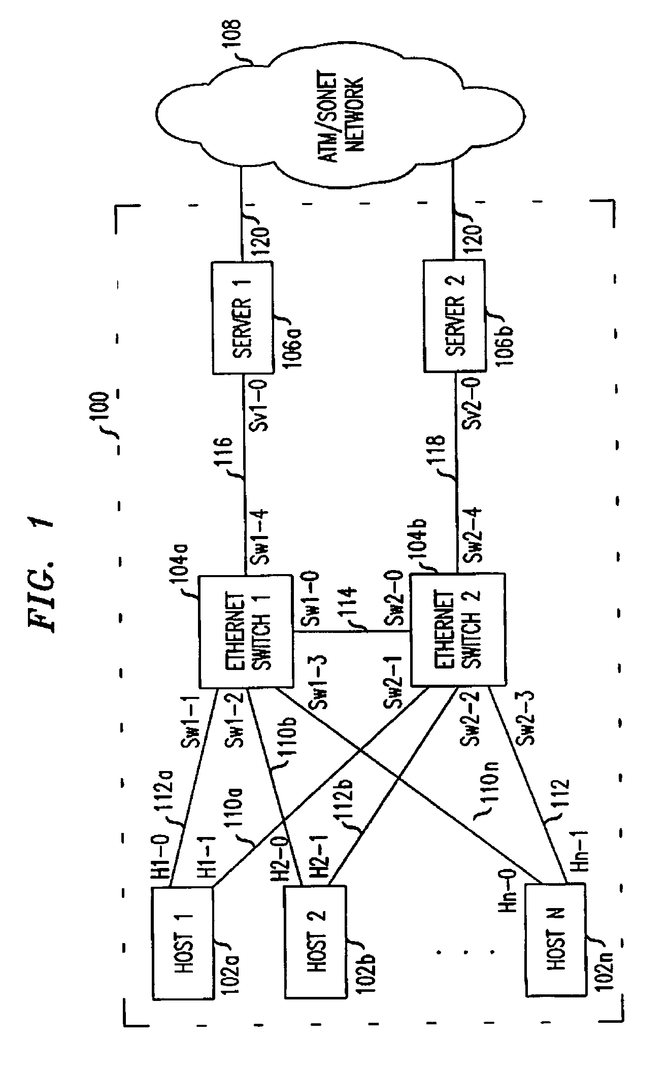
[0014]FIG. 1 shows by way of example and not limitation, an Ethernet LAN 100 interconnecting a plurality of hosts 102, Ethernet switches 104a, 104b and a pair of servers 106a, 106b. For example, the Ethernet LAN 100 may reside within a Radio Network Controller (RNC)) as known in mobile telecommunication systems such as Universal Mobile Telecommunications System (UMTS) or CDMA2000, which RNC is typically connected to an ATM / SONET network. In such case, the hosts 102 comprise traffic processors that perform, among other things, frame selection functions and which send messages to other parts of the system.

[0015]The servers 106a,b operate as an active-standby pair (as shown, Server 1 is active, Server 2 is standby) such that if the active server fails or the link supported by the active server fails, the standby server will take over. For convenience, the hosts 102 are further identified as “Host 1” to “Host N,” the switches “Ethernet Switch 1” and “Ethernet Switch 2” and the servers ...


PUM


Abstract

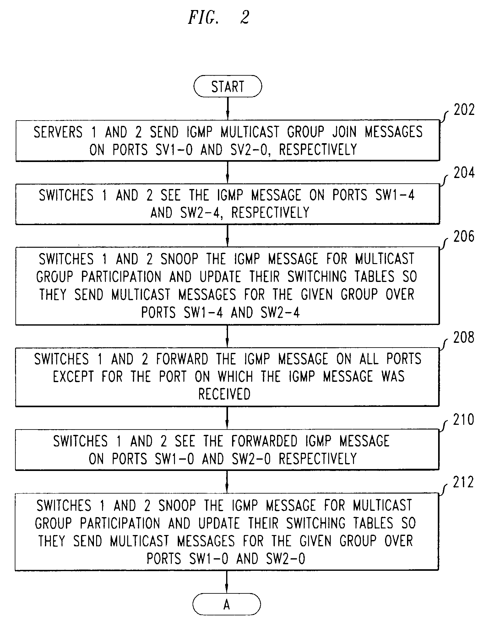
Multi cast techniques are employed to provide host computer elements access to multiple redundant servers of a communication network in such a way that the hosts need not know which of the servers is active. In one embodiment, the servers provide a gateway function between an Ethernet LAN and an external network. The Ethernet LAN comprises one or more hosts connected to one or more switches, the switches connected to corresponding servers defining an active / standby pair. The servers are connected to an external network by corresponding active / standby links. The hosts send messages directed to a multicast address to at least one of the switches. The switches forward the messages on ports according to a multicast routing topology having been determined by performing IGMP “snooping” of messages issued from the servers. Both the active and standby servers receive the messages; and the active server sends the messages to the external network. In case the active server fails or is removed from service, the standby server is promoted to active server and assumes the role of the formerly active server without necessitating any communication to the hosts to inform them of the change in status of the active server.

Description

FIELD OF THE INVENTION[0001]This invention relates generally to communication networks and, more particularly, to communication networks having two or more servers.BACKGROUND OF THE INVENTION[0002]Communication networks, such as Local Area Networks (LANs), are known to interconnect communication devices spanning a limited geographical area (such as within a building or campus) by a physical medium, such as coax, twisted pair, fiber optic cable or wireless medium. Generally, LANs include multiple endpoints (or “hosts”), such as computers or computer elements sharing a common communication protocol such as, for example, Internet Protocol (IP). Oftentimes, LANs include gateway / server nodes (hereinafter “servers”) for performing certain algorithmic functions requested by the hosts. For example, servers may perform a “gateway” function linking the LAN to external networks that use different communication protocol(s), such that messages may be communicated between the hosts and the extern...

Claims


Application Information

Patent Timeline
IPC IPC(8): H04L12/28H04J3/26H04L12/18
CPCH04L12/1886H04L12/1836H04L12/185
Inventor GERDISCH, MITCHELL RRUBIN, HARVEY
Owner RPX CORP
Learn More