MPLS network system

a network system and multi-protocol technology, applied in data switching networks, time-division multiplexing selection, multiplex communication, etc., can solve the problems of fresh problems, inability to ensure the sequence of frames belonging to the single flow in the routing process, and inability to achieve load sharing, so as to enhance the load sharing

Inactive Publication Date: 2007-12-11
FUJITSU LTD
View PDF4 Cites 8 Cited by
  • Summary
  • Abstract
  • Description
  • Claims
  • Application Information

AI Technical Summary

Benefits of technology

[0037]It is a primary object of the present invention to provide a technique of capable of enhancing a load sharing effect without causing a reverse of sequence when an edge node (egress edge node) receiving MPLS frames in an MPLS network allocates packets (frames) to a plurality of physical links bundled as one logical link in a way that refers to only MPLS headers.

Problems solved by technology

As a result, a problem is that the sequence of the frames belonging to the single flow can not be assured in the process of routing.
This leads to a problem in which the load sharing is not attained.
This approach therefore causes a fresh problem.
Under such a circumstance that the various categories of protocols can be stacked on MPLS, the problem is that the header analysis per protocol is required, and this process is time-consuming.
Further, there is lost the MPLS's fundamental merit that MPLS enables packet routing based on only the MPLS header, and therefore the approach described above has the problem.

Method used


Image

  • MPLS network system
  • MPLS network system
  • MPLS network system

Examples


modified example

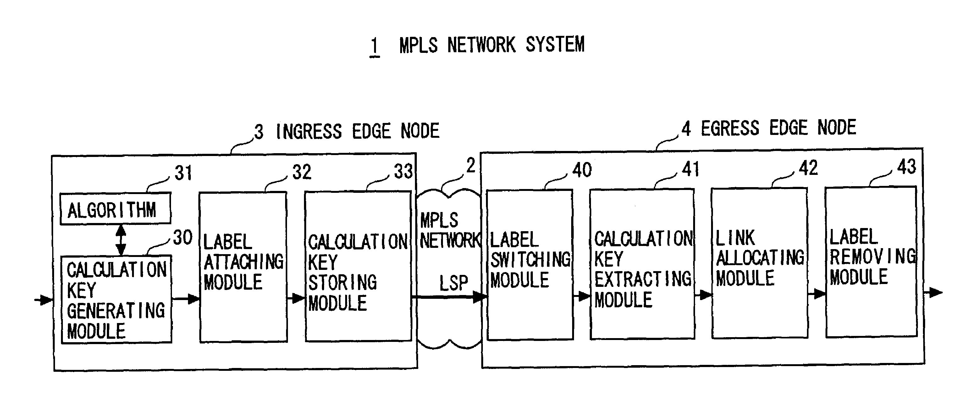
[0211]One embodiment discussed above has exemplified the case in which the calculation key generating module 30 in the ingress edge node 3 generates the calculation key on the basis of the source IP address and the destination IP address contained in the IP header corresponding to the third layer (network layer) of OSI (Open Systems Interconnections) Reference Model. The calculation targets may, however, be set to a protocol field value in the IP header, a protocol header on the fourth layer (transport layer) of OSI Reference Model, and also source identifying information and destination identifying information contained in the header unique to application such as HTTP (HyperText Transfer Protocol).

[0212]The respective processes in one embodiment discussed above are provided as a program executable by the computer, and the program may be recorded on a recording medium such as a CD-ROM, a flexible disk etc and may also be distributed via communication lines.


PUM


Abstract

A first edge node in an MPLS network system includes a generation module generating a key value for determining an allocating destination link in a way that uses, as input values, a piece of source identifying information and a piece of destination identifying information contained in a header of a forwarding target frame before being attached with an MPLS header enabling the frame to be forwarded across an MPLS network on the basis of an MPLS protocol, an embedding module embedding the key value generated by the generation module into a specified field in the MPLS header, and a transmitting module transmitting the MPLS frame containing the key value embedded into the specified field in its MPLS header to the MPLS network.

Description

BACKGROUND OF THE INVENTION[0001]The present invention relates generally to a communication device for allocating packets to a plurality of physical links that are logical bundled, and more particularly to an MPLS (Multi Protocol Label Switching) network system schemed to enhance a load sharing effect without causing a reverse of sequence when allocating the packets to the plurality of physical links bundled as they appear to be one logical link by referring to only headers of MPLS frames in an egress edge node in an MPLS network.[0002]MPLS has been watched with keen interest as a technique of speeding up a packet forwarding process (packet switching process) in an IP (Internet Protocol) network such as the Internet. MPLS is the protocol enabling a forwarding target packet such as an IP packet to be routed based on a 20-bit label attached to this packet inside the MPLS network in a way that assembles an MPLS frame by attaching an MPLS header containing the 20-bit label to the packet...

Claims


Application Information

Patent Timeline
Patent Type & Authority Patents(United States)
IPC IPC(8): H04L12/56H04L45/50H04L47/41H04Q11/00H04Q11/04
CPCH04L45/00H04L45/502H04L45/50H04Q2011/0077
Inventor KUBOTA, MAKOTOTSURUOKA, TETSUMEI
Owner FUJITSU LTD
Why Eureka
Try Eureka