Antenna adaptation in a time division duplexing system

a technology of time division and duplexing, applied in the direction of power management, transmission monitoring, site diversity, etc., can solve the problems of increasing noise, interference becomes a problem, and crowding of radio spectrum, so as to reduce the performance of all users, and achieve the effect of reducing noise and nois

Inactive Publication Date: 2007-12-11
IPR LICENSING INC
View PDF16 Cites 48 Cited by
  • Summary
  • Abstract
  • Description
  • Claims
  • Application Information

AI Technical Summary

Benefits of technology

[0020]In further aspects, the optimum directional settings may be stored in a register, memory, or other storage device and read out in synchronism with known assigned active time slots. Thus, a system which requires the antenna to be steered to a particular direction in a given time slot may be readily steered to another optimum direction in the next adjacent time slot.

Problems solved by technology

Unfortunately, having tens, if not hundreds, of closely spaced networks means that interference becomes a problem.
That is, although the most emerging wireless standards provide for robust signaling in the form of spread spectrum radio frequency modulation, or using Code Division Multiple Access (CDMA) over modulated subcarriers, crowding of the radio spectrum still increases noise and therefore decreases performance for all users.
The capacity of CDMA networks which use a frequency reuse factor of one is limited by both intercell and intracell interference.
Users in adjacent cells or sectors also cause intercell interference on the uplink (UL) or reverse direction.

Method used


Image

  • Antenna adaptation in a time division duplexing system
  • Antenna adaptation in a time division duplexing system
  • Antenna adaptation in a time division duplexing system

Examples


Embodiment Construction

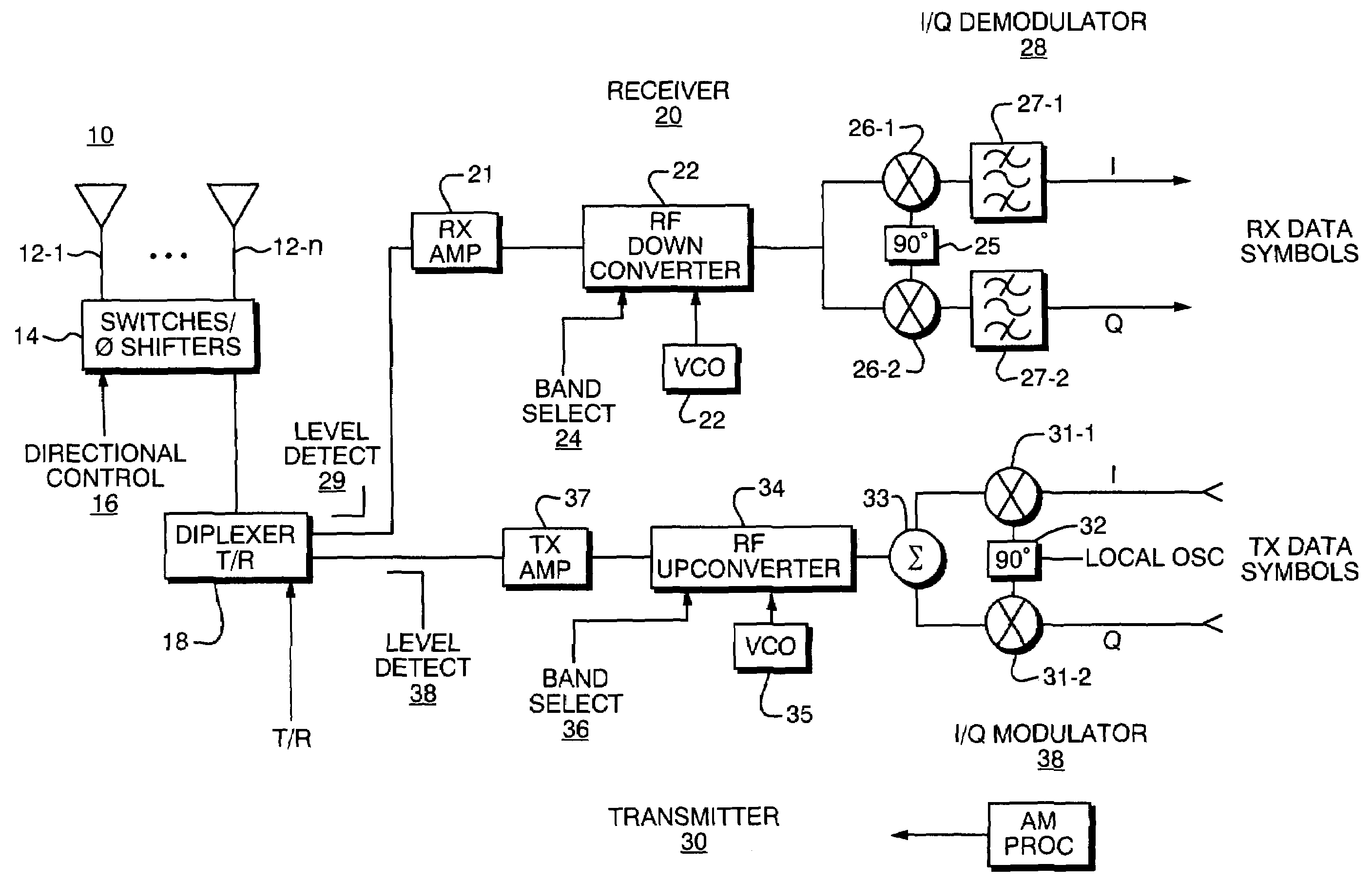
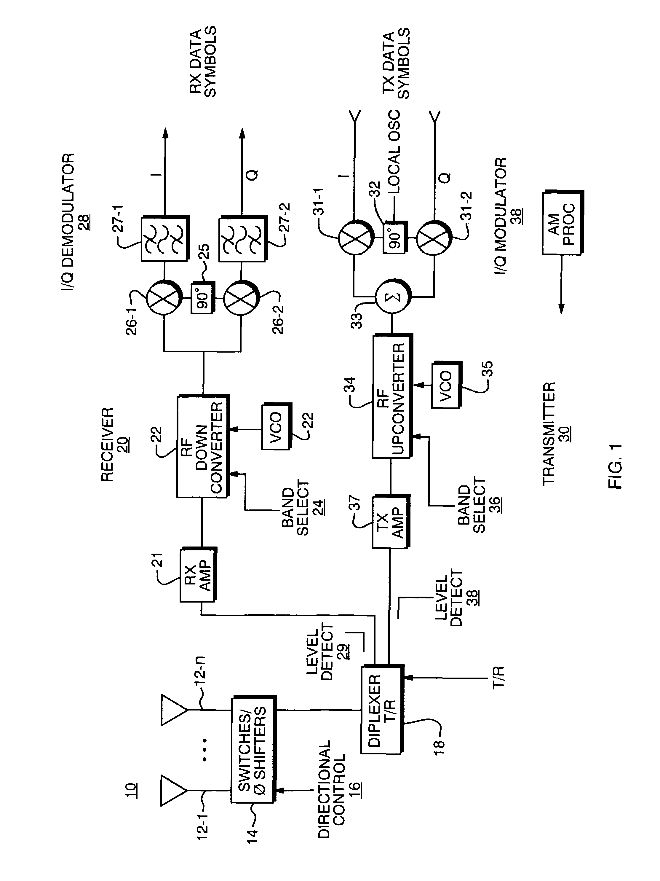
[0035]A description of one preferred embodiment of the invention follows. This particular embodiment is for a cellular wireless communication system that is known as Universal Mobile Telephone System (UMTS) Wideband Code Division Multiple Access (W-CDMA) as specified in the Telecommunications Industry Association (TIA) T1.3GPP.25 series of specifications; it should be understood that the principles of the invention may be applied to other types of wireless systems, however.

[0036]Basic Operation

[0037]In any cellular system there is generally a central Base Transceiver Station (BTS) or access point (AP), that communicates to remote units, or User Equipment (UE). Any such system is bi-directional in nature, that is, it must provide the ability to communicate from the BTS to the UE (downlink) and from the UE to the BTS (uplink). The duplexing of the uplink and downlink communication channels may be performed in two primary ways. These are Frequency Division Duplexing (FDD) and Time Divi...


PUM


Abstract

A technique for steering a directional antenna such as may be used with User Equipment (UE) in a wireless communication system. Optimum angle settings for the directional antenna are determined as different values for an uplink and downlink; that is for simple reception and simple transmission. Thus, rather than determine compromised directions that are picked in an attempt to optimize transmission and reception with the same directional setting, directional settings may be optimized independently. The invention is of particular use in a Time Division Duplex (TDD) system where transmit and receive functions can be operating independently at different times. In further aspects, an optimum direction is determined by estimating an interference signal power which is detected from signals emanating from adjacent base stations (access points) and determining a directional setting that minimizes interference to adjacent cells based upon such measurements. A further level of sophistication in antenna angle setting, is to monitor the loading of adjacent cell sites base stations and turning interference and determine the settings accordingly to minimize interference to such heavily loaded neighbors. Further aspects of the invention adapts to acquisition modes that accommodate the directional setting in active use of the system.

Description

RELATED APPLICATIONS[0001]This application claims the benefit of U.S. Provisional Application No. 60 / 378,698, filed on May 7, 2002, U.S. Provisional Application No. 60 / 378,908, filed on May 7, 2002 and U.S. Provisional Application No. 60 / 466,535 filed on Apr. 29, 2003, entitled “Application of User Equipment Antenna to Time Division Duplex System”, all of which are assigned to Tantivy Communications Corporation, the assignee of this application. The entire teachings of the above applications are incorporated herein by reference.BACKGROUND OF THE INVENTION[0002]Wireless data communication networks of various types, including digital cellular systems, Wireless Local Area Networks (WLANs) and even personal area networks such as Bluetooth are increasingly viewed as an ideal connectivity solution for many different applications. These can be used to provide access to wireless equipped personal computers within home networks, mobile access to laptop computers and personal digital assistan...

Claims


Application Information

Patent Timeline
Patent Type & Authority Patents(United States)
IPC IPC(8): H04M1/00H04B7/26H04B7/005H04B7/02H04B17/00H04W52/08H04W52/24H04W52/28H04W52/40H04W52/42
CPCH01Q3/26H04W52/08H04W52/143H04W52/146H04B17/327H04W52/24H04W52/18H04B7/022H04W52/242H04W52/283H04W52/40H04W52/42H04W52/243
Inventor NELSON, JR., GEORGE RODNEYPROCTOR, JR., JAMES A.REGNIER, JOHN A.
Owner IPR LICENSING INC
Why Eureka
Try Eureka