Electric power tool

a technology of electric power tools and power tools, applied in the field of electric power tools, can solve problems such as malfunction, deterioration of operability, idleness of internal gears, etc., and achieve the effects of excellent operability, excellent operability, and excellent operability

Inactive Publication Date: 2007-12-18
MAKITA CORP
View PDF29 Cites 98 Cited by
  • Summary
  • Abstract
  • Description
  • Claims
  • Application Information

AI Technical Summary

Benefits of technology

[0066]a ball fitted to the cam groove to connect the spindle and the hammer and allowing the backward movement of the hammer by rolling in the cam groove.
[0081]According to the present invention, any of all operation modes can be selected by operating a common switching means. Accordingly, malfunction can be prevented and operability and reliability can be excellent.
[0082]Moreover, adding the percussion drill mode does not deteriorate operability, so that an excellent operability can be maintained.
[0083]Further, since a common switching means is also used for switching speed, a more excellent operability can be expected.
[0084]Still further, each switching member can be surely slid to a sliding position smoothly.
[0085]Still further, biasing the output shaft to a forward position as well as the chuck sleeve to a backward position can be achieved by using one biasing means, which reduces the number of parts and achieves an efficient structure. Therefore, the trouble of assembly can be saved and the manufacture cost can be reduced.

Problems solved by technology

That is, when a load to the anvil exceeds to a biasing force of the coil spring, the internal gear is caused to idle to stop rotation transmission to the anvil.
When the selectable modes are thus increased, an impact switching member for switching between an impact mode and a drill mode, a clutch switching member for switching between the drill mode and the clutch mode, and a percussion switching member for switching between the drill mode and a percussion drill mode have to be separately manufactured, so that operability is deteriorated and malfunction might occur.
As a result, the number of parts increases and thus structure is complicated, which makes assembly troublesome and the cost high.

Method used


Image

  • Electric power tool
  • Electric power tool
  • Electric power tool

Examples


Embodiment Construction

[0096]Hereinafter, a preferred embodiment of the present invention will be explained with reference to the drawings.

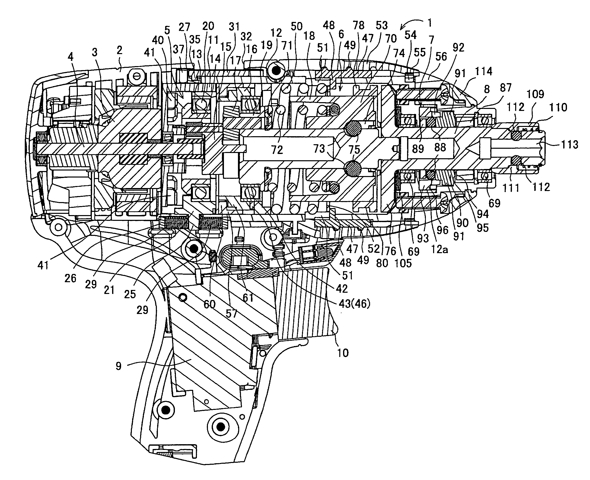
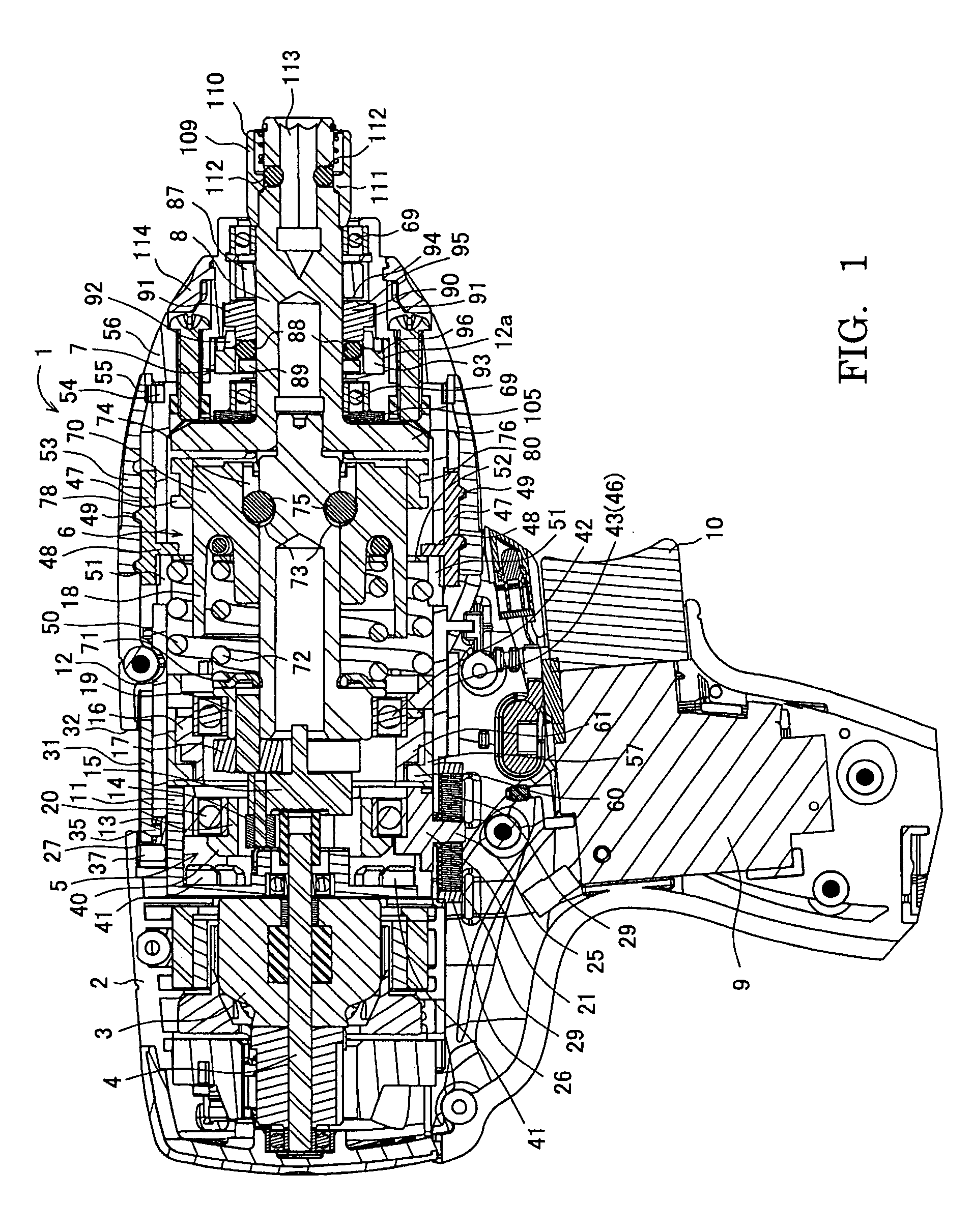
[0097]FIG. 1 is a vertical section view of an impact driver as an example of an electric power tool. An impact driver 1 has a motor 3 accommodated at the rear of a body housing 2 formed of a pair of right and left half-housings. (Here, the right direction of FIG. 1 is forward.) In front of the motor 3, a planetary gear reduction mechanism 5 with a clutch mechanism, an impact mechanism 6 and a percussion mechanism 7 are respectively provided, and an anvil 8 coaxially provided with a motor shaft 4 of the motor 3 is protruding at the front end. The reference number 9 denotes a switch of a driving circuit for the motor 3, and the reference number 10 denotes a trigger for turning ON the switch 9 when the trigger is pressed.

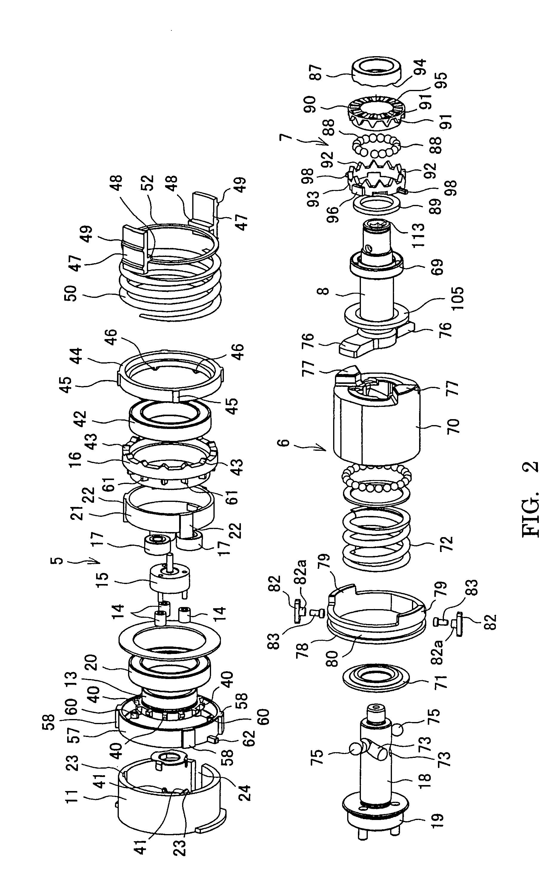
[0098]As shown in FIGS. 2 and 3, the planetary gear reduction mechanism 5 is housed between a cylindrical motor bracket 11 and a gear case 12. The motor ...


PUM


Abstract

An electric power tool is provided which prevents malfunction with excellent operability even when one operation mode among various modes is selectable. In a gear case of a housing, there are provided a clutch switching groove which engages with a connecting projection of a clutch switching lever, a slit which guides a guide body having a stepped pin which penetrates an impact switching groove to engage with an auxiliary ring, and a percussion switching groove which engages with a connecting projection of a percussion switching lever. In addition, a switching case is externally provided, so that combination of sliding positions of each switching member can be changed. As the switching case can be operated by a switching button, any of all operation modes, which are, a drill mode, an impact mode, a percussion drill mode, and a clutch mode can be selected with the switching button only.

Description

[0001]This application claims the benefit of Japanese Patent Application Numbers 2004-314598 and 2004-314599 filed on Oct. 28, 2004, the entirety of which are incorporated by reference.BACKGROUND OF THE INVENTION[0002]1. Field of the Invention[0003]The present invention relates to an electric power tool capable of applying the intermittent impact, percussion in the axial direction and the like to an anvil protruding to the front of a housing by selecting an operation mode.[0004]2. Description of the Related Art[0005]As an electric power tool, an impact tool described in Japanese laid-open patent application No. 2000-317854 is well known. In this application, rotation of an output shaft of a motor is transmitted to a driving shaft in a housing through a planetary gear reduction mechanism, and a hammer biased forward by a coil spring is externally provided with the driving shaft through a ball. Then, by engaging the hammer with an arm of an anvil (an output shaft) protruding to the fr...

Claims


Application Information

Patent Timeline
Patent Type & Authority Patents(United States)
IPC IPC(8): B25B23/159
CPCB25B21/00B25B21/02B25B21/023B25B21/026B25B23/14B25B23/141B25D11/106B25D16/003B25D16/006B25D11/08Y10T279/17068B25D2216/0023B25D2216/0038Y10T279/17888
Inventor FURUTA, TAKEFUMI
Owner MAKITA CORP
Why Eureka
Try Eureka