Drainable base course for a landfill and method of forming the same

a landfill and drainable technology, applied in water cleaning, excavations, roads, etc., can solve the problems of affecting the environmental environment, affecting the drainage effect, and affecting the drainage effect, and achieve the effect of forming the same, and reducing the cost of forming

Inactive Publication Date: 2007-12-18
ADVANCED GEOTECH SYST
View PDF19 Cites 17 Cited by
  • Summary
  • Abstract
  • Description
  • Claims
  • Application Information

AI Technical Summary

Benefits of technology

[0025]It is therefore an object of the present invention to provide economical means and methods for providing drainage to landfills and other large structures.
[0028]In accordance with these and other objects of the invention, a series of landfills are provided having synthetic drainable base courses for controlling the flow of fluids such as liquids and gases within landfills and other large structures, and for draining landfills and other large structures, are provided. In one preferred embodiment, a landfill or other large structure according to the invention preferably comprises a base layer formed at least partially of one or more of native soil components and non-native soil components, a synthetic drainable base course element disposed above the base layer, wherein the drainable base course element comprises a void-maintaining geocomposite, the geocomposite including a geocomposite core element having a plurality of ribs constructed and arranged to form a plurality of interconnected voids, the core element having an upper surface and a lower surface, a no-load thickness and a thickness under load, wherein the thicknesses are measured substantially perpendicular to the surfaces, and at least one fluid-transmissible layer attached adjacent the upper surface, wherein the layers and the core element are constructed and arranged so that, under a load of at least 500 lbs / foot2 for a period of at least 100 hours, the geocomposite maintains voids of sufficient dimension that fluid from the landfill or other large structure can move freely through portions of the drainage element at a transmissivity of at least 19 gallons / minute / foot at a slope gradient of 33% and at least 33 gallons / minute at a slope gradient of 10%, and, above the synthetic drainable base course, fill suitable to be drained, the fill comprising one or more layers, sections or quantities of refuse materials, or materials to be processed at least partially within the landfill, wherein at least a portion of the synthetic drainable base course is sloped downwardly in a gradient from a first portion to a second portion of the landfill or other large structure.
[0031]As a further advantage, ribs of the geocomposite can be provided in whatever numerous cross-sectional shape and length variations which are necessary to achieve the drainage capacities of a particular landfill or other large structure, such as an airport runway, a runway runoff zone, a parking lot, a temporary runway, a building, or a buried antenna site. Included in such cross-sectional shapes are those where the ribs approximate one or more shapes from the group consisting of squares, rectangles, ovals, star shapes, crenulations, and trapezoids. Dimensions of the ribs can be tailored to provide desired capacities, economies, and installation characteristics.

Problems solved by technology

It is well established that leachate can cause distress and damage to synthetic liner systems, causing leaks, and thereby polluting groundwater and the local environment.
Therefore, even when stones are subjected to compressive forces, voids exist in those spaces where the stones do not touch.
Typically, the more porous an installation or layer, the higher the resulting cost.
For example, engineers may require a stone drainage layer to achieve the regulatory requirements but the local geological conditions do not offer stone.
When this occurs, contractors are required to purchase stone and have it transported over long distances.
Such transportation costs significantly drives up the cost of construction of the landfill.
In fact, engineers and other design personnel who procure construction aggregates typically estimate that the cost of aggregate supply doubles for every 25 miles of transport distance to the landfill site.
Thus, inadequate drainage can be an extremely serious and costly problem affecting a landfill.
An OGBC can be costly to install and maintain, and can be difficult to control and predict with respect to quality.
Although such gradations of stone typically create interconnecting void spaces or holes among and between the aggregate useful to facilitate the reception and transmission of fluid, an OGBC can take up a considerable volume of valuable space of the installation.
An additional problem relates to the longevity of the chosen stone.
Other disadvantages of OGBC's pertain to the additional elements that are required in an OGBC installation.
This extra filter layer further increases the construction costs of the landfill.
Yet another problem with the use of OGBC's is that aggregate of sufficient quality is not always available or, if available, it's cost is uneconomical or prohibitively high.
Conventional edge drain geosynthetics, however, cannot withstand the repeated dynamic loads that are present directly beneath heavy overburdens, such as those typically found in land fills and other large structures.
However, such geosynthetic products have never been engineered to achieve flow rates and void-maintaining capabilities sufficient to replace stone.

Method used


Image

  • Drainable base course for a landfill and method of forming the same
  • Drainable base course for a landfill and method of forming the same
  • Drainable base course for a landfill and method of forming the same

Examples


Embodiment Construction

[0052]The present invention may be understood with respect to the following figures which are exemplary and not exclusive. As one of skill in the arts will appreciate, numerous embodiments of the present invention are within the scope and spirit of the present disclosure.

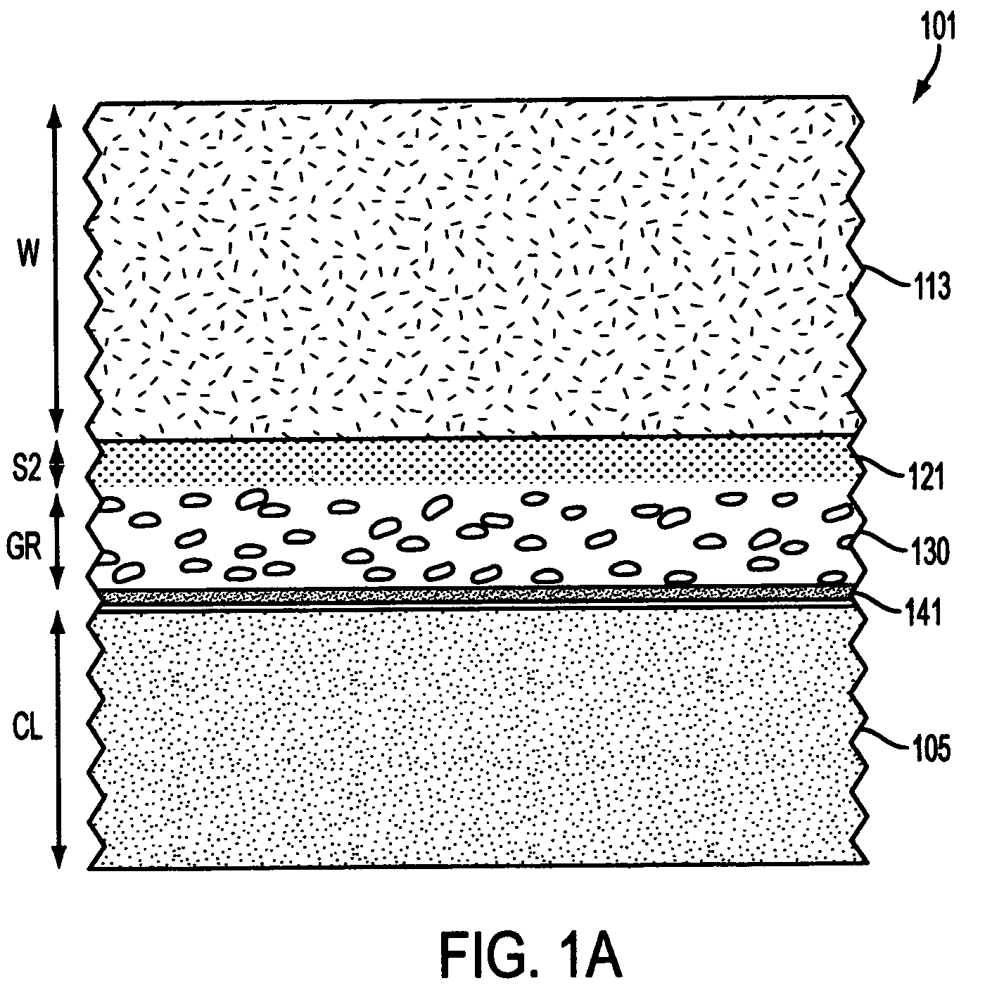
[0053]FIG. 1(a) shows an idealized cross-section of a conventional design of a municipal solid waste system with conventional minimum liner system. With reference to FIG. 1(a), municipal solid waste system 101 comprises clay liner or base 105, of thickness CL, which is typically a minimum of 600 millimeters (“mm”). Base 105 is topped by conventional geomembrane 141. In turn, conventional geomembrane 141 is covered with gravel layer 130, of thickness GR, typically a minimum of 300 mm. Gravel layer 130 is covered with conventional sand layer 121, of thickness S, typically a minimum of 150 millimeters. Sand layer 121 is covered with waste overburden 113, of thickness W, and typically from several meters to several doze...


PUM


Abstract

Numerous embodiments of one or more layers of void-maintaining synthetic drainable base courses (“VMSDBC's”) are provided as incorporated into landfills and other waste containment facilities.

Description

RELATED APPLICATIONS[0001]The present application is a Continuation-In-Part of U.S. patent application Ser. No. 10 / 232,811, filed Sep. 3, 2002, now U.S. Pat. No. 6,802,669, granted Oct. 12, 2004. The present application also claims priority to U.S. patent application Ser. No. 09 / 501,324, filed Feb. 10, 2000, now U.S. Pat. No. 6,505,996, granted Jan. 14, 2003; to U.S. patent application Ser. No. 09 / 501,318, filed Feb. 10, 2000 (now abandoned); and U.S. Provisional Application No. 60 / 316,036, filed Aug. 31, 2001. The cited Applications are hereby incorporated by reference in their entireties.FIELD OF THE INVENTION[0002]The present invention pertains to means and methods for controlling the flow of fluids, such as gases and aqueous liquids through, and for evacuating fluids from, landfills and other large structures. The invention provides improved and novel drainage elements and systems of geosynthetic void-maintaining synthetic drainable base courses (“SDBC”) which can be installed e...

Claims


Application Information

Patent Timeline
Patent Type & Authority Patents(United States)
IPC IPC(8): B09B5/00E01C3/00E01C3/06E01F5/00E02B11/00E02D31/02E02D31/10E02D31/14
CPCE01C3/00E01C3/06E01F5/00E02B11/00E02D31/10E02D31/14E02D31/02E02D2450/108E02D2300/0085
Inventor IANNIELLO, PETER J.ZHAO, AIGENSHAFFER, GARY L.
Owner ADVANCED GEOTECH SYST
Why Eureka
Try Eureka