Reflective encoder with light shield and electronic device using such reflective encoder

a technology of reflective encoder and light shield, which is applied in the direction of electric discharge lamps, photoelectric discharge tubes, instruments, etc., can solve the problems of reducing the amount of light emitted by the light emitting element that reaches the light detecting element, the effect of reducing the amount of light emitted by the light emitting element, and improving the output waveform of optical signals

Inactive Publication Date: 2007-12-18
SHARP KK
View PDF15 Cites 78 Cited by
  • Summary
  • Abstract
  • Description
  • Claims
  • Application Information

AI Technical Summary

Benefits of technology

[0017]The present invention has been achieved with consideration of the above-described facts, and it is an object thereof to provide reflective encoders that are capable of improved optical properties through the elimination of undesired signals by a light shielding body, and to provide more compact, more accurate electronic devices through the incorporation of such reflective encoders.
[0018]A reflective encoder of the present invention is provided with a light emitting portion having a light emitting element capable of irradiating light and a light emitting side transparent resin body for covering and protecting the light emitting element, a light detecting portion having a light receiving element for detecting light that is irradiated from the light emitting element and that is reflected by a reflecting region of a code wheel, and a light receiving side transparent resin body for covering and protecting the light receiving element, and a light shielding body arranged between the light emitting side transparent resin body and the light receiving side transparent resin body for separating the light emitting portion and the light detecting portion. As a result, the light from the light emitting portion side is prevented from directly entering the light detecting portion side by the light shielding body, and thus undesired signals in the light receiving element can be eliminated.
[0019]The reflective encoder of the present invention may be further provided with a secondary mold resin portion for fixing the light emitting portion and the light detecting portion, so as to maintain a predetermined distance, wherein the light shielding body is molded in a single piece with the secondary mold resin portion. In the case of such a configuration, it is possible both to form the light shielding body without increasing manufacturing steps, and to accurately position the light emitting portion and the light detecting portion.

Problems solved by technology

Thus, precision loss due to internal reflection is a significant problem.
Furthermore, from the result of experiments, it has been found that the undesired signal that directly enters the light detecting element from the light emitting element induces a noise component shift in the output signal waveform that is about ⅙ the amplitude of the output signal waveform.
As above, the problem of the effect due to internal reflection is greater with reflective encoders than with reflective photo interrupters.
On the other hand, there is also the problem that if the distance between the lens of the light emitting element and the lens of the light detecting element is large, then the amount of light emitted by the light emitting element that reaches the light detecting element is reduced.

Method used


Image

  • Reflective encoder with light shield and electronic device using such reflective encoder
  • Reflective encoder with light shield and electronic device using such reflective encoder
  • Reflective encoder with light shield and electronic device using such reflective encoder

Examples


embodiment 1

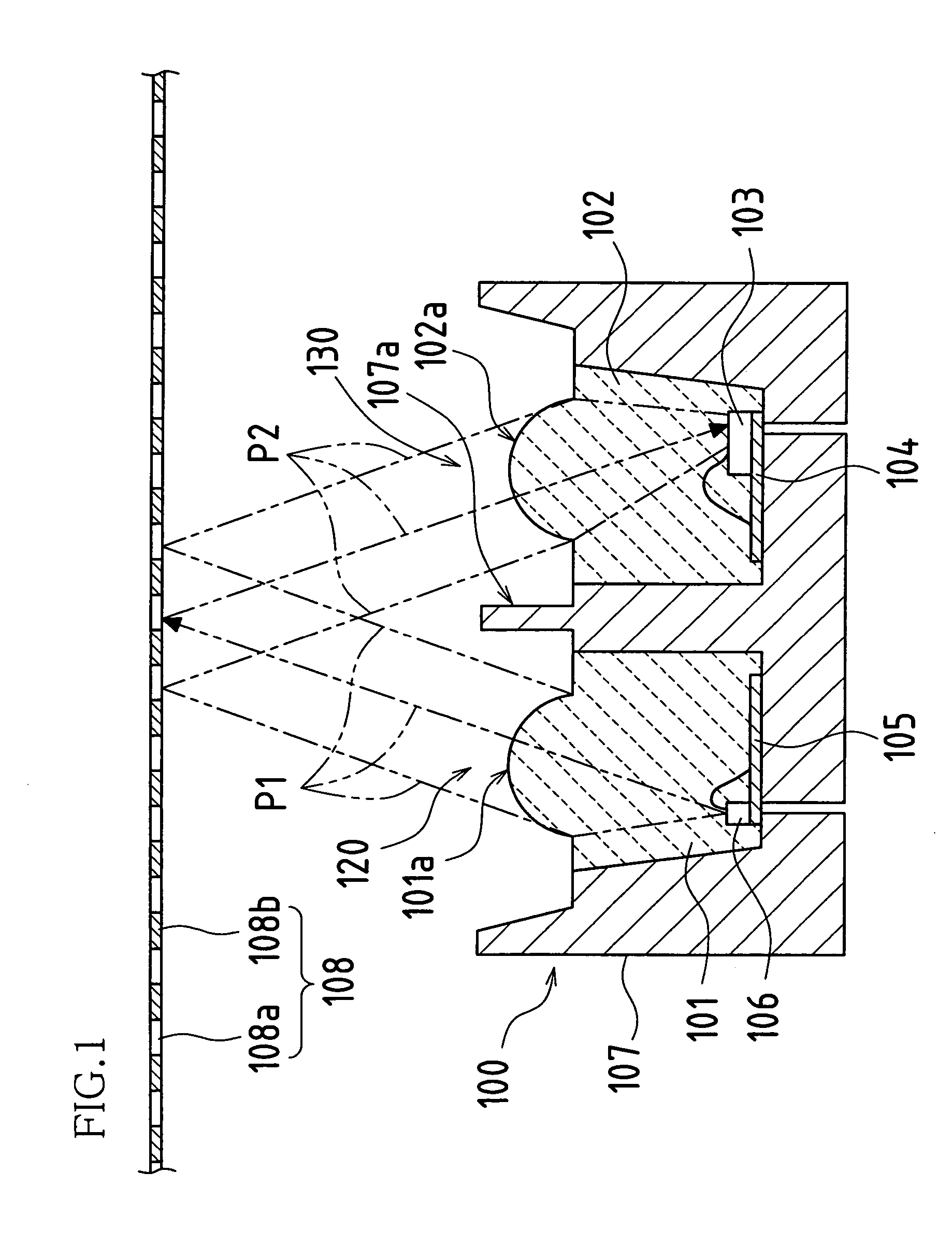
[0044]FIG. 1 is a cross-sectional view showing a reflective encoder 100 associated with Embodiment 1 of the present invention, and FIG. 2 is a perspective view of the reflective encoder 100 of FIG. 1.

[0045]The reflective encoder 100 is provided with a light emitting portion 120, a light detecting portion 130, and a secondary mold resin portion 107 that fixes the light emitting portion 120 and the light detecting portion 130, for positioning the light emitting portion 120 and the light detecting portion 130.

[0046]The light emitting portion 120 has a light emitting side frame 105, a light emitting element 106 arranged on the light emitting side frame 105 and a light emitting side transparent resin body 101 that covers and protects the light emitting element 106. The upper portion of the light emitting side transparent resin body 101 is molded into a light emitting side lens 101a. The light detecting portion 130 has a light receiving side frame 104, a light receiving element 103 arrang...

modified example of embodiment 1

[0051]An embodiment in which a light emitting element and a light receiving element are directly mounted on the same substrate is described next with reference to the drawings.

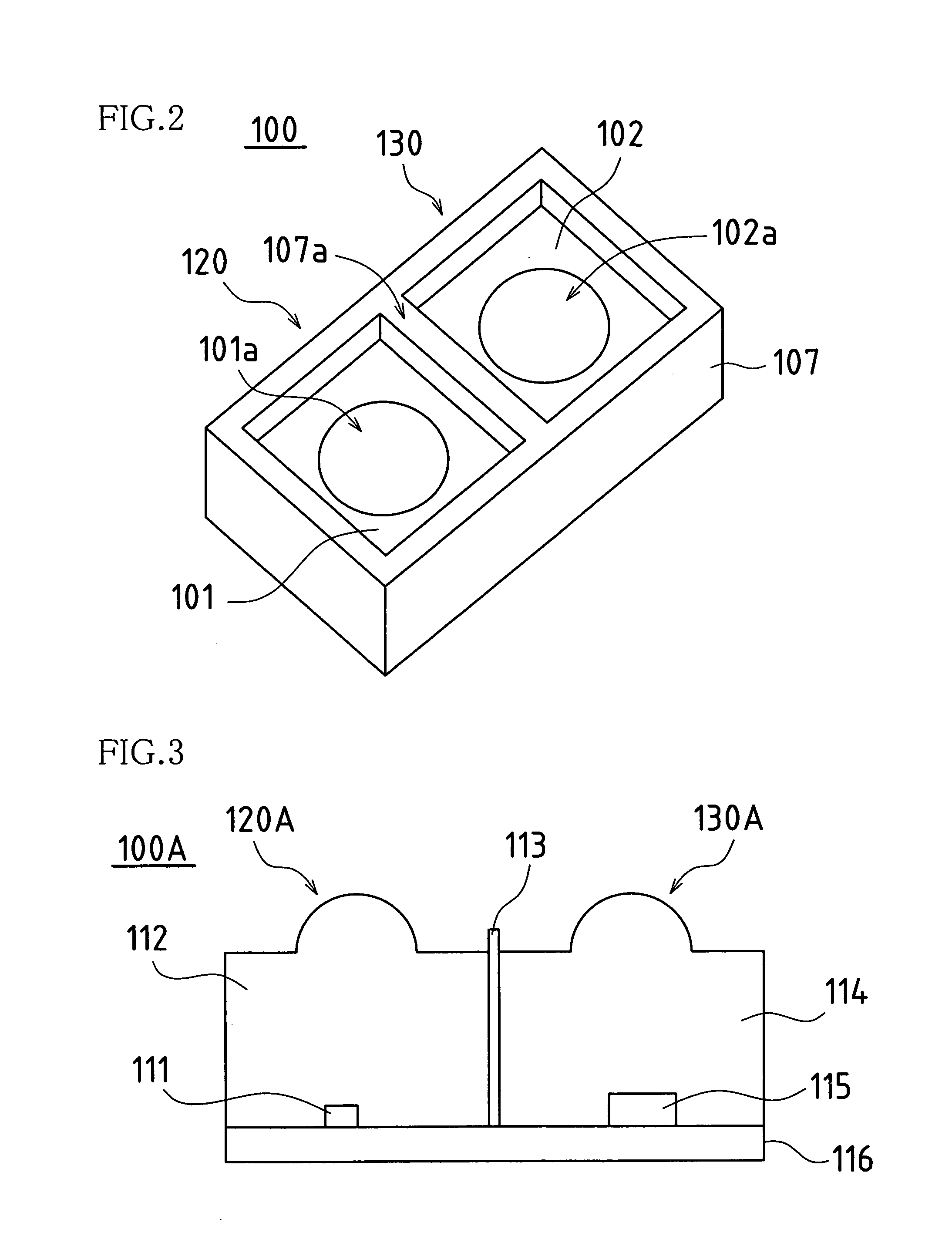
[0052]FIG. 3 is a cross-sectional view showing a reflective encoder 100A associated with a modified example of Embodiment 1 of the present invention.

[0053]In the reflective encoder 100A, a light emitting element 111 and a light receiving element 115 are mounted on a single substrate 116. The light emitting element 111 and the light receiving element 115 are covered by a light emitting side transparent resin body 112 and a light receiving side transparent resin body 114 respectively. A light shielding body 113 formed using an opaque resin is arranged on the boundary part between the light emitting side transparent resin body 112 and the light receiving side transparent resin body 114.

[0054]Because the reflective encoder 100A has such a configuration, the light emitted from a light emitting portion 120A (portion...

embodiment 2

[0056]Embodiment 2 of the reflective encoder of the present invention is described next with reference to the drawings.

[0057]FIG. 4 is a cross-sectional view showing a reflective encoder 200 associated with Embodiment 2 of the present invention.

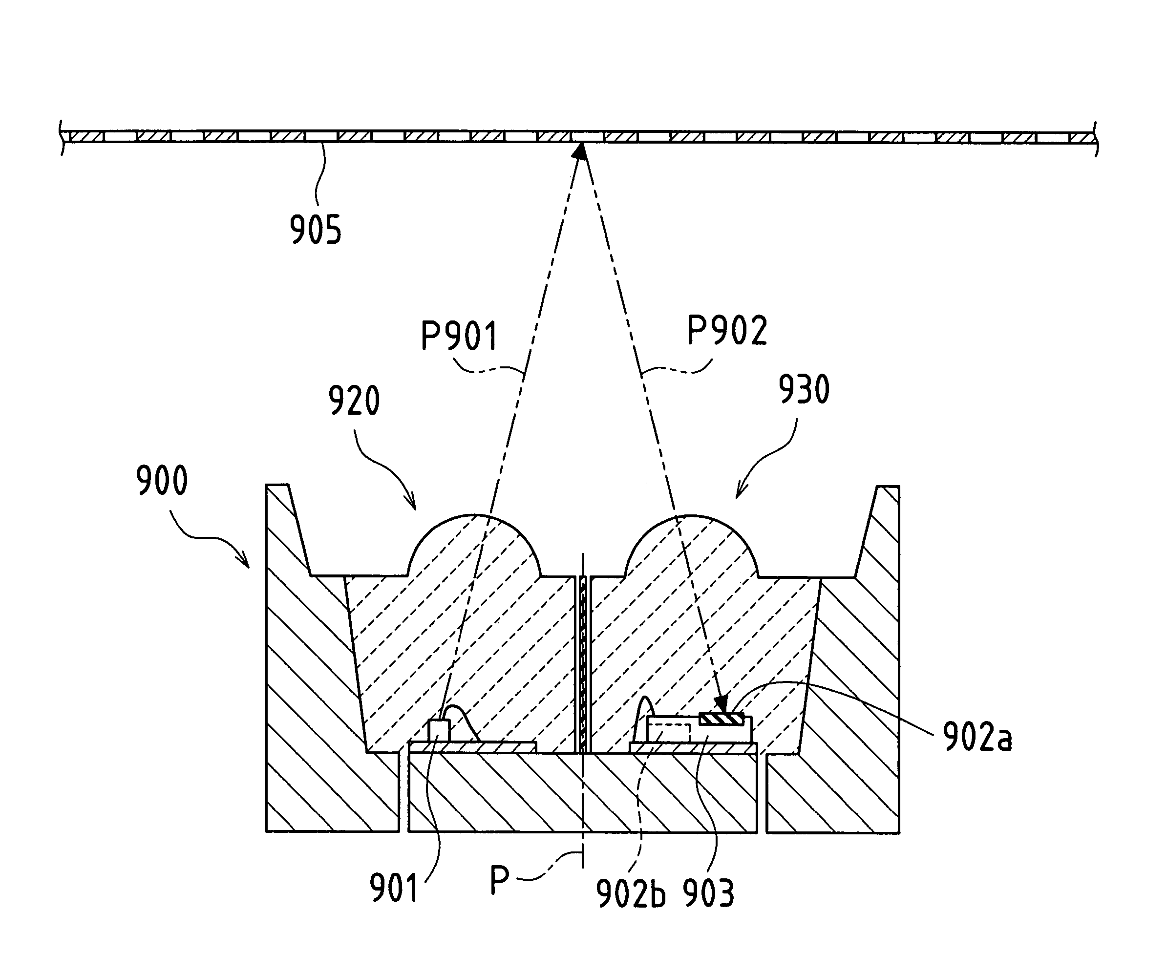
[0058]In the reflective encoder 100 of Embodiment 1, the light shielding body 107a is molded in a single piece with the secondary mold resin portion 107, however in this case, if the light shielding body 107a does not have a certain thickness then there may be a problem, for example, in that the resin does not penetrate, resulting from the step of molding of the resin. Therefore, it is necessary to set the thickness of the light shielding body 107a such that the resin sufficiently penetrates. As a result, the distance between the light emitting portion 120 and the light detecting portion 130 may increase, possibly leading to a decrease in the optical properties such as the amount of light entering the light detecting portion 130 from the ligh...


PUM


Abstract

A reflection encoder is disclosed having a light emitting element in a light receiving element that are separated by a light shielding body that prevents unwanted light from entering the light receiving element. In variations of the invention, the light shielding body may be integrally formed with a mold resin portion that holds the light emitting element and light receiving element, formed by a sheet or plate, or formed using an opaque liquid resin that is poured between transparent resin bodies that encapsulate the light emitter and receiver. In operation, light radiated from the light emitting element is reflected by a code wheel and then received by a light receiving element. Other variations include varying the height at which the light receiving and detecting elements are disposed relative to the code wheel and tilting these elements towards each other so as to increase light efficiency.

Description

CROSS REFERENCE TO RELATED APPLICATIONS[0001]This application claims priority under 35 U.S.C. § 119(a) on Patent Application No. 2004-217495 filed in Japan on Jul. 26, 2004, the entire contents of which are hereby incorporated by reference.BACKGROUND OF THE INVENTION[0002]1. Field of the Invention[0003]The present invention relates to a reflective encoder, which is an optical system of an optical sensor used as a part of an optical shaft angle encoder for generating an electric signal to indicate the angular position or angular change of a shaft.[0004]2. Description of the Related Art[0005]FIG. 11 shows a structural example of a conventional reflective encoder.[0006]The reflective encoder is an optical encoder provided with a capsule-shaped reflective sensor 1100 that detects a modulated light beam Pa1102 that is reflected from reflective regions 1104a of a code wheel 1104. The reflective sensor 1100 includes a light emitting element 1101 that illuminates the reflective regions 1104...

Claims


Application Information

Patent Timeline
Patent Type & Authority Patents(United States)
IPC IPC(8): G01D5/34H01L27/14
CPCG01D5/305G01D5/34H01L31/02325H01L31/167H01L2224/48091H01L2924/3025H01L2924/1815H01L2924/00014H01L2924/00
Inventor NAGASAKA, KOHJISHICHI, KOHICHISASAKI, MASATO
Owner SHARP KK
Why Eureka
Try Eureka