Motor drive circuitry with regenerative braking for disk drive

a technology of regenerative braking and motor drive, which is applied in the direction of motor/generator/converter stopper, dynamo-electric converter control, stopping arrangement, etc., can solve the problems of limited battery life, large differences between these conditions, and considerable cost into the system supply

Inactive Publication Date: 2007-12-18
WESTERN DIGITAL TECH INC
View PDF15 Cites 24 Cited by
  • Summary
  • Abstract
  • Description
  • Claims
  • Application Information

AI Technical Summary

Benefits of technology

[0008]According to another aspect of the invention, a circuit controls power supplied to a spindle motor and a head motor of a disk drive from a voltage source coupled to first and second voltage supply nodes, during normal operation the circuit provides a conduction path through a switching element to a motor supply node, and includes a spindle motor drive circuit and a head drive motor drive circuit that provide conduction paths from the motor supply node to the second voltage supply node to energize the spindle motor and the head motor. The circuit further includes a control circuit that operates at specified times during normal operation to cause the switching element to prevent current flow between the first voltage supply node and the motor supply node, configure the spindle motor drive circuit to cease driving the spindle motor and allow the spindle motor to supply current to the motor supply node, and configure the head motor drive circuit to energize the head motor with current flowing from the first voltage supply node and current supplied by the spindle motor.

Problems solved by technology

One problem facing system integrators who design systems consisting of hard disk drives (HDDs) is to design power supplies capable of meeting both peak and average load conditions.
In systems containing many HDDs, the differences between these conditions can become quite large, especially when considering that many drives may be simultaneously acting under their peak load conditions.
Considerable cost may go into those system supplies in order to maintain reliable operation well beyond the statistical average load.
A second problem then is the design tradeoff in the electromechanical system that is made to compromise power consumption for improved access time.
This design tradeoff may relate to a third problem of limited battery life for mobile applications.

Method used


Image

  • Motor drive circuitry with regenerative braking for disk drive
  • Motor drive circuitry with regenerative braking for disk drive
  • Motor drive circuitry with regenerative braking for disk drive

Examples


an embodiment

Structure of an Embodiment

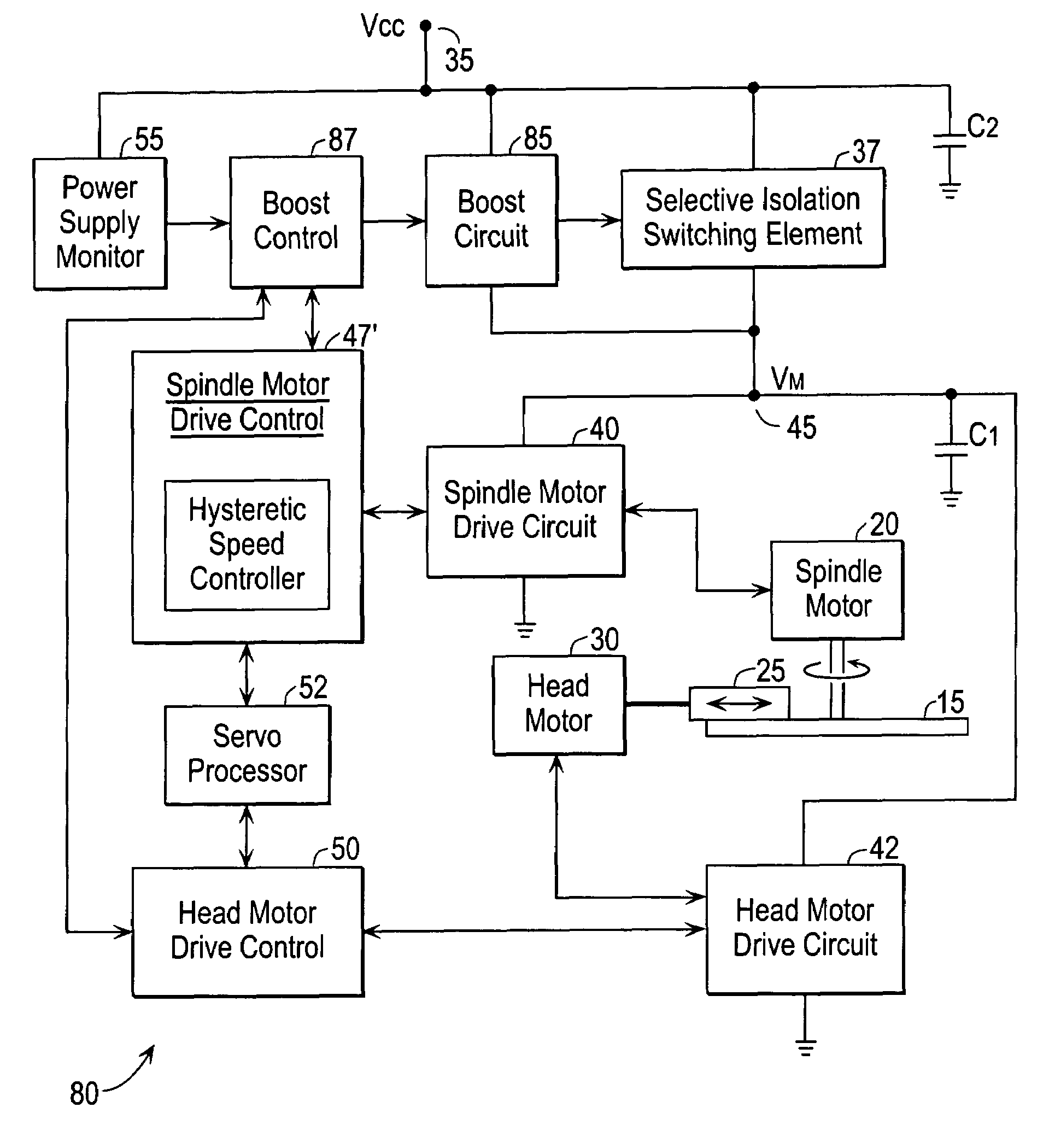
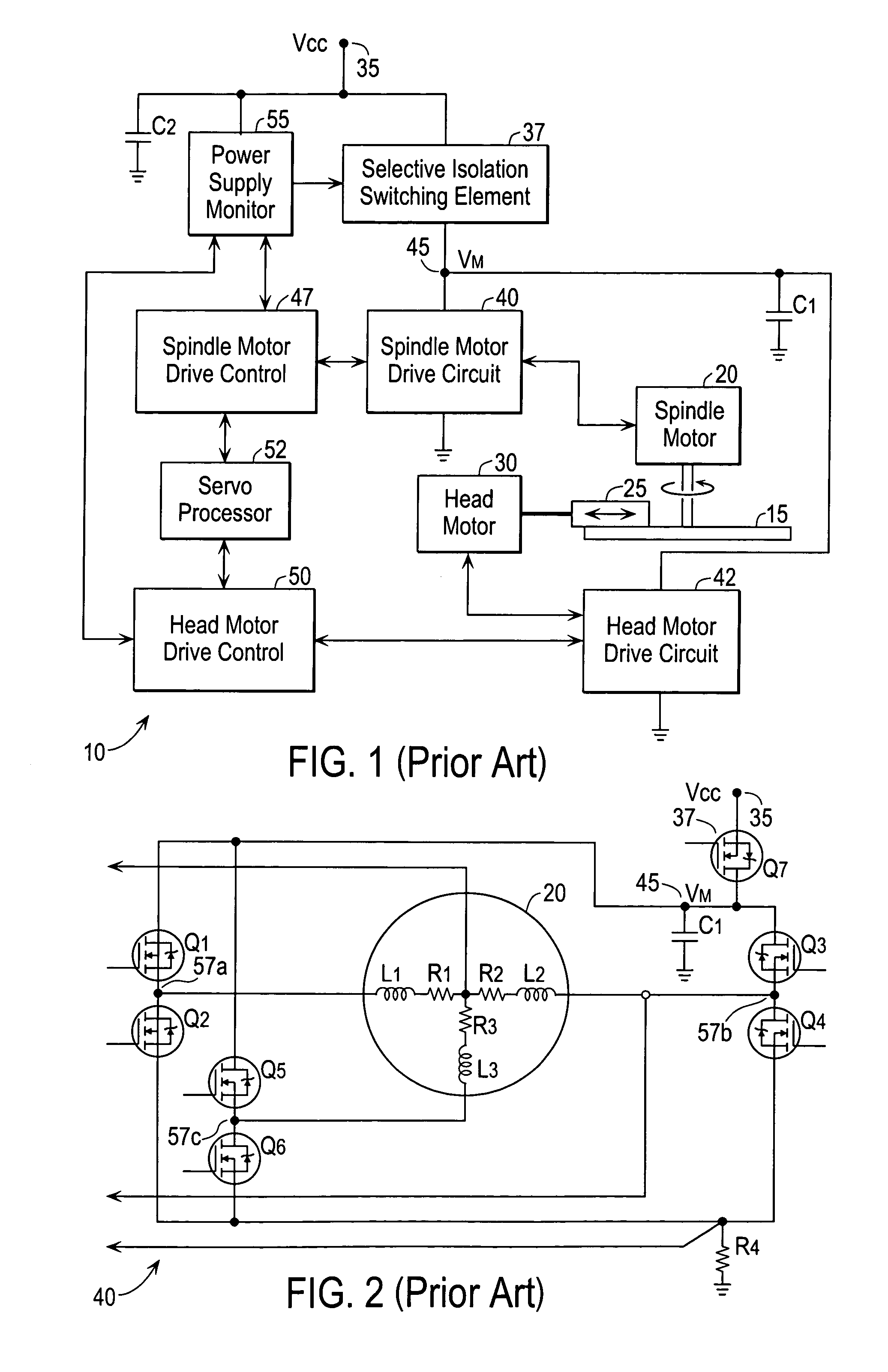
[0059]FIG. 5 is a block diagram of a system 80 for powering and controlling a disk drive according to an embodiment of the present invention. This embodiment represents an enhancement of the conventional system shown in FIG. 1, and as such corresponding elements are shown with corresponding reference numerals. In short, embodiments of the invention provide a regenerative braking mode that is invoked during normal operation. As mentioned above, in this context, normal operation means that power to the disk drive is within acceptable limits and that further read and / or write operations are contemplated. For example, embodiments of the present invention provide the ability to increase the drive current to head motor 30 during seek operations by entering the regenerative braking mode. This mode entails operating spindle motor 20 as a generator, and converting its stored kinetic energy into additional power to drive head motor 30. In some instances, for battery-...


PUM

PropertyMeasurementUnit
mechanical rotationaaaaaaaaaa
frequencyaaaaaaaaaa
commutation frequencyaaaaaaaaaa

Abstract

During normal operation of a hard disk drive, control logic controls a plurality of switching elements to provide electrical power to a spindle motor and head motor of the disk drive from a voltage source coupled to first and second voltage supply nodes (e.g., Vcc and ground), the spindle motor has a set of motor windings to which the electric power is applied to rotate the spindle motor, and the control logic is configured to enter a regenerative braking state during normal operation where the switching elements are controlled to isolate the spindle motor from the first voltage supply node and cause regenerative braking of the spindle motor so that kinetic energy due to rotation of the spindle motor is converted to electrical power that is supplied to the head motor by virtue of inductance of one or more motor windings in the set.

Description

BACKGROUND OF THE INVENTION[0001]The present invention relates generally to disk drives, and more specifically to techniques for providing power to the motors in a disk drive. Most of the discussion will concentrate on the example of hard disk drives (HHDs).[0002]One problem facing system integrators who design systems consisting of hard disk drives (HDDs) is to design power supplies capable of meeting both peak and average load conditions. In systems containing many HDDs, the differences between these conditions can become quite large, especially when considering that many drives may be simultaneously acting under their peak load conditions. Considerable cost may go into those system supplies in order to maintain reliable operation well beyond the statistical average load. Minimizing the difference between peak and average load currents eases design requirements for such system power supplies.[0003]Additionally, the peak load from the perspective of the mechanics of the HDD involve...

Claims


Application Information

Patent Timeline
Patent Type & Authority Patents(United States)
IPC IPC(8): H02P3/14H02P3/18G11B19/20G11B19/28G11B21/10H02P6/24
CPCG11B19/20H02P6/24G11B19/28
Inventor MOSER, MICHAEL A.ROWAN, BRYAN S.YU, MANTLE
Owner WESTERN DIGITAL TECH INC
Why Eureka
Try Eureka