Temperature-compensated circuit for power amplifier using diode voltage control

a voltage control and temperature compensation technology, applied in the field of power amplifiers, can solve the problems of cost-effective and efficient manufacturing of portable electronic devices, and achieve the effect of efficient design and cost-effective manufactur

Active Publication Date: 2007-12-18
WAVICS
View PDF33 Cites 10 Cited by
  • Summary
  • Abstract
  • Description
  • Claims
  • Application Information

AI Technical Summary

Benefits of technology

[0029]To solve the above problems, the present invention provides a temperature-compensated circuit for a power amplifier having a circuit to control a diode voltage of a bias circuit to compensation for a temperature of the power amplifier.

Problems solved by technology

With the development of electronic technologies, portable electronic apparatuses are efficiently designed and costly effectively manufactured.
Thus, it is a problem that the voltage VY must be less than 2.4V to perform accurate temperature compensation so that the static operational current IQ of the transistor Q2 is constantly maintained.

Method used


Image

  • Temperature-compensated circuit for power amplifier using diode voltage control
  • Temperature-compensated circuit for power amplifier using diode voltage control
  • Temperature-compensated circuit for power amplifier using diode voltage control

Examples


Embodiment Construction

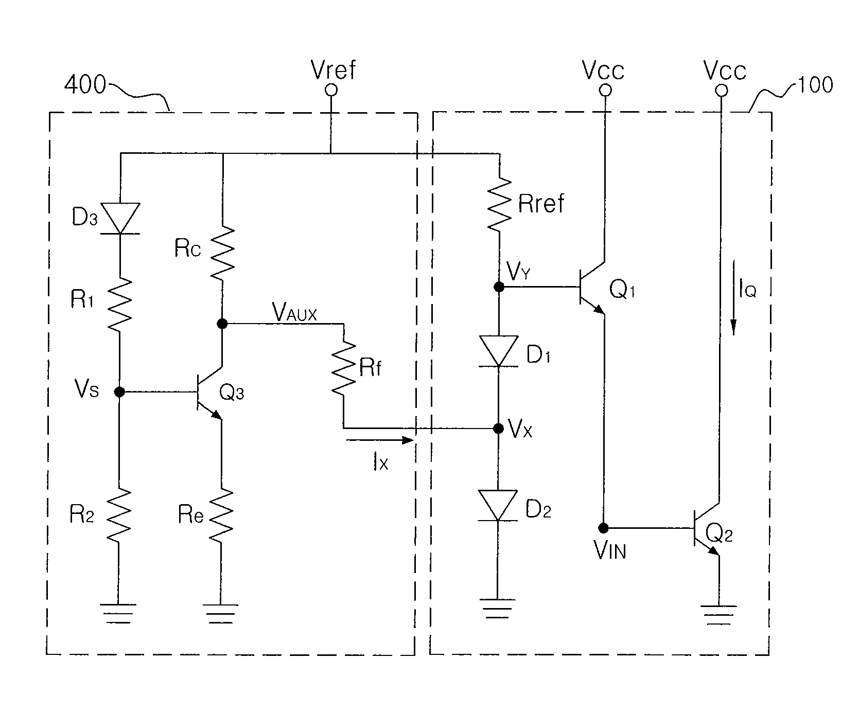
[0046]In the present invention, the additional temperature compensation in a wider range is possible, as shown in FIG. 5, by designing a circuit which operates to absorb reference current when temperature increases and source reference current when temperature decreases.

[0047]The present invention includes methods of maintaining a value of the static operational current IQ at the room temperature as shown in a curve shown in FIG. 5 (Mode 1), maintaining the value of the static operational current IQ at the highest temperature within a range allowed by the specification (Mode 2), and continuously maintaining the value of the static operational current IQ at the lowest temperature within the range allowed by the specification (Mode 3).

[0048]In Mode1, current at a lower / higher temperature with respect to the room temperature is up / down. In Mode 2, current at a relatively lower temperature with respect to a higher temperature is up. In Mode 3, current at a relatively higher temperature ...


PUM


Abstract

Provided is a temperature-compensated circuit for a power amplifier through diode voltage control, in which a first resistor (Rref), a first diode (D1), and a second diode (D2) are connected to a reference voltage in series. The temperature-compensated circuit includes a second resistor (R1) connected to the reference voltage, a third resistor (R2) connected to the second resistor in series, a fourth resistor (Rc) having one terminal connected to the reference voltage, a fifth resistor (Re) having one terminal connected to ground, a bias transistor having a base terminal connected to a contact point (VS) between the second resistor and the third resistor, a collector terminal connected to the other terminal of the fourth resistor, and an emitter terminal connected to the other terminal of the fifth resistor, and a sixth resistor (Rf) connected between a series connection terminal between the first diode and the second diode, and the collector terminal of the bias transistor. The voltage of the collector terminal changes for compensation of a temperature.

Description

[0001]This application claims priority under 35 U.S.C. § 119 to Korean patent application number 10-2004-0073492, filed Sep. 14, 2004, which is incorporated by reference along with all other references cited in this application.BACKGROUND OF THE INVENTION[0002]1. Field of the Invention[0003]The present invention relates to a power amplifier included in a personal portable communication device such as a cellular phone or a personal digital assistant (PDA), and more particularly, to a temperature-compensated circuit for a power amplifier.[0004]2. Description of the Related Art[0005]With the development of electronic technologies, portable electronic apparatuses are efficiently designed and costly effectively manufactured. The portable electronic apparatuses largely include pagers, cellular phones, music players, calculators, laptop computers, and PDAs. The portable electronic apparatuses generally require DC power and one or more batteries are used as an energy source for supplying DC...

Claims


Application Information

Patent Timeline
Patent Type & Authority Patents(United States)
IPC IPC(8): G05F3/02H03F3/04
CPCH03F1/30H03F1/0261H03F1/302H03F2200/18H03F2200/447
Inventor JEON, JOOYOUNGKIM, JUNGHYUN
Owner WAVICS
Why Eureka
Try Eureka