Electro-optic reflective element assembly

a reflective element and optical technology, applied in the direction of instruments, lighting and heating apparatus, semiconductor devices for light sources, etc., can solve the problems of difficult electrical contact between the semi-conductive and/or conductive layers of the substrate, and achieve the effect of improving the assembly process

Inactive Publication Date: 2007-12-18
DONNELLY CORP
View PDF135 Cites 164 Cited by
  • Summary
  • Abstract
  • Description
  • Claims
  • Application Information

AI Technical Summary

Benefits of technology

[0016]Therefore, the present invention provides an electro-optic or electrochromic cell or mirror reflective element assembly that provides an overhang region at least one edge of the front substrate for electrical connection to the conductive layer at the rear surface of the substrate, such that the electrical connection is not viewable through the front surface of the front substrate. The present invention thus may provide a reflective element assembly that is suitable for use in a bezelless mirror assembly, where the front surface of the reflective element is substantially entirely viewable by a driver of the vehicle. Optionally, a reflective element assembly of the present invention may provide a flush alignment of an upper and / or lower edge of a pair of substrates, while providing clearance for electrical connection to the upper and / or lower edges of one of the substrates and the respective conductive coating. The present invention thus provides enhanced assembly processes for the mirror element, since the substrates may be aligned with one another within an assembly fixture and do not require stepped pins or spacers positioned along one edge to provide sufficient offset or staggering between the substrates to provide clearance for electrical connection to one of the substrates along the aligned or flush edge thereof.

Problems solved by technology

In cells or reflective element assemblies that may provide a small bezel or no bezel, it is often difficult to make electrical contact to the semi-conductive and / or conductive layers of the substrates with a restricted overhang between the substrates.

Method used


Image

  • Electro-optic reflective element assembly
  • Electro-optic reflective element assembly
  • Electro-optic reflective element assembly

Examples


Embodiment Construction

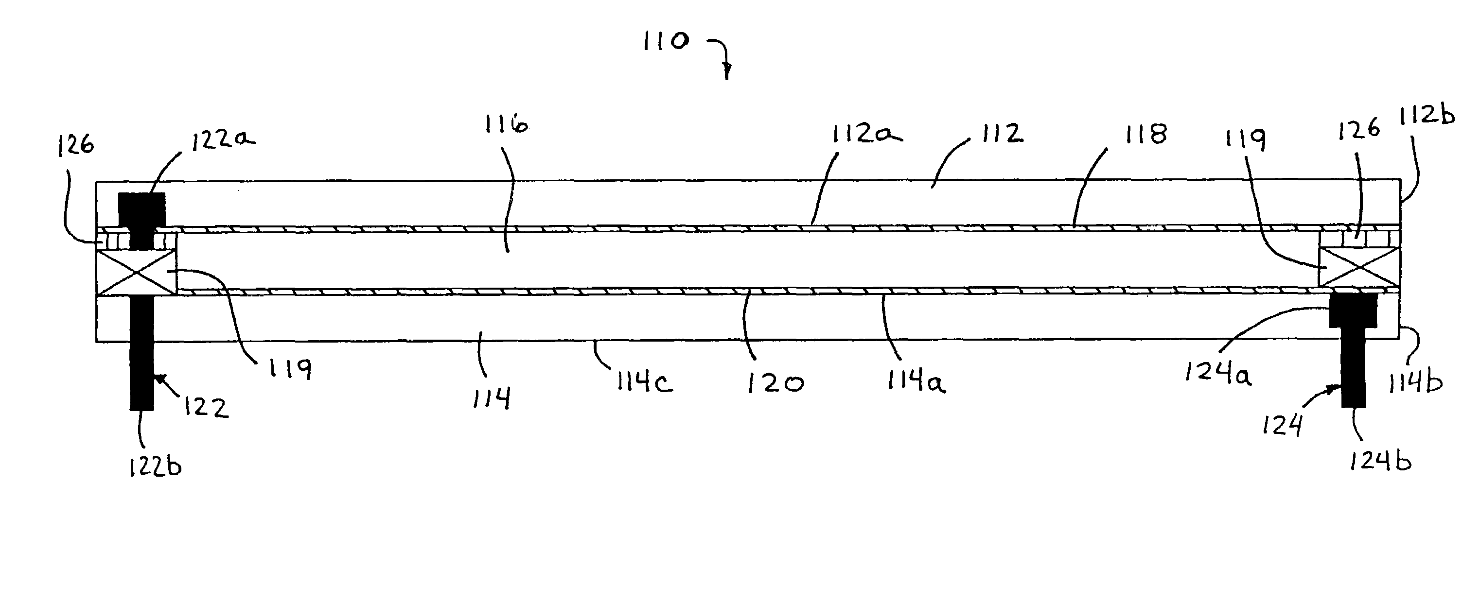
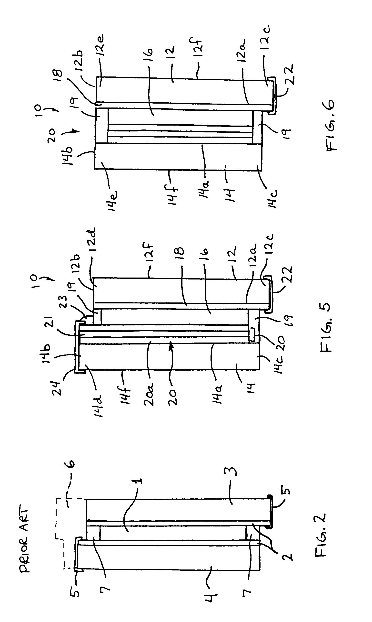
[0059]Referring now to the drawings and the illustrative embodiments depicted therein, an electro-optic or electrochromic cell or mirror element assembly or reflective element assembly 10 for an interior rearview mirror assembly of a vehicle (not shown) includes first and second glass substrates 12, 14 and an electro-optic or electrochromic medium 16 disposed or sandwiched therebetween (FIGS. 4-6). Electrochromic medium 16 and at least one metallic and / or non-metallic conductive or semi-conductive layers 18, 20 are disposed on the inner surfaces 12a, 14a of substrates 12, 14 and between the electrochromic medium 16 and the respective substrate 12, 14. At least one of the edges or sides 12b, 14b of the substrates 12, 14 are generally aligned with or flush with one another (as seen in FIGS. 4 and 6) at least along a portion of the edges. The reflective element or mirror element of the present invention is equally suitable for interior or exterior rearview mirror assemblies for vehicle...


PUM

PropertyMeasurementUnit
sheet resistanceaaaaaaaaaa

Abstract

A rearview mirror assembly for a vehicle includes an electro-optic reflective element with an overhang region at an edge region of a first substrate that extends beyond a corresponding edge region of a second substrate. A transparent electrical conductor is disposed at a second surface of the first substrate and a mirror reflector is disposed at a third surface of the second substrate. The mirror reflector includes a tab portion that at least partially encompasses an edge dimension of the second substrate. A non-conductive seal is disposed between the first and second substrates and encompasses at least a portion of the mirror reflector and at least a portion of a non-conductive perimeter region of the third surface. A first electrical connector connects to the transparent electrical conductor via the overhang region and a second electrical connector is in electrical connection with the tab portion of the mirror reflector.

Description

CROSS REFERENCE TO RELATED APPLICATIONS[0001]The present application is a continuation of U.S. patent application Ser. No. 10 / 533,762, filed May 4, 2005 now U.S. Pat. No. 7,184,190, which is a 371 U.S. national phase application of PCT Application No. PCT / US2003 / 035381, filed Nov. 5, 2003, which claims priority of U.S. provisional applications, Ser. No. 60 / 490,111, filed Jul. 25, 2003 by McCabe et al. for FLUSH ELECTROCHROMIC CELL; and Ser. No. 60 / 423,903, filed Nov. 5, 2002 by McCabe for ONE SIDED FLUSH ELECTROCHROMIC CELL; and U.S. patent application Ser. No. 10 / 533,762 is a continuation-in-part of U.S. pat. application Ser. No. 10 / 528,269, filed Mar. 17, 2005, which is a 371 application of PCT Application No. PCT / US2003 / 029776, filed Sep. 19, 2003, which claims priority of U.S. provisional applications, Ser. No. 60 / 412,275, filed Sep. 20, 2002 by McCabe for ELECTROCHROMIC MIRROR ASSEMBLY; Ser. No. 60 / 424,116, filed Nov. 5, 2002 by McCabe for ELECTROCHROMIC MIRROR ASSEMBLY; and Se...

Claims


Application Information

Patent Timeline
Patent Type & Authority Patents(United States)
IPC IPC(8): G02F1/15
CPCG02F1/157B60Q1/2665B60R1/088F21K9/30B60Q1/24G02F1/155G02F1/161G02F1/163F21Y2103/003F21Y2103/10F21Y2115/10F21S43/14B60R1/1207B60Q1/34B60Q2400/40B60R1/04B60R1/06G02B5/0875G02B5/10
Inventor MCCABE, IAN A.VARAPRASAD, DESARAJUHABIBI, HAMIDLYNAM, NIALL R.
Owner DONNELLY CORP
Why Eureka
Try Eureka