Electromagnetic wave generator

a generator and electromagnetic technology, applied in the direction of x-ray tube targets, convertors, instruments, etc., can solve the problems of difficult to implement high-current acceleration, difficult to repeatedly collide with and the beam off the closed orbit cannot stably circulate. , to achieve the effect of high intensity, short time, and high speed

Inactive Publication Date: 2007-12-18
MITSUBISHI ELECTRIC CORP
View PDF5 Cites 5 Cited by
  • Summary
  • Abstract
  • Description
  • Claims
  • Application Information

AI Technical Summary

Benefits of technology

[0012]The present invention has been implemented in order to cope with the problems discussed above, and realizes a compact and low-cost electromagnetic wave generator in which, compared with a conventional electromagnetic wave generator, high intensity X-rays can be generated and the energy of generated X-rays can be switched at high speed.
[0013]An electromagnetic wave generator and an electromagnetic-wave generation method according to the present invention are characterized in that, in a circular accelerator including an electron generator for generating electrons, an injector for injecting electrons from the electron generator, an accelerator for accelerating the injected electrons, a deflection electromagnet for generating a deflection magnetic field to deflect the injected electrons or accelerated electrons, and a target with which the accelerated electrons are made to collide, whereby electromagnetic waves are generated, the shape of the deflection electromagnet enables a focusing function for injected electrons or accelerated electrons, the circular accelerator has electron closed orbits that, through the deflection electromagnet having the focusing function, are situated in a region with a predetermined width in the radial direction thereof and stable during the entire process including an injection step and an acceleration step, the target is arranged across the stable electron closed orbits and, in accordance with the arrangement position of the target, a collision region where a circulating electron beam collides with the target and at least one region that is adjacent to the collision region and in which a circulating electron beam does not collide with the target are formed, within the stable electron closed orbits, and through control of respective patterns of changes with time in a deflection magnetic field created by the deflection electromagnet and in electron-beam acceleration, a given electron closed orbit is shifted between the collision and the non-collision regions, whereby the target and a circulating electron beam collide with each other, thereby generating electromagnetic waves.
[0014]With the electromagnetic wave generator according to the present invention, electron beams that stably circulate along different orbits can be made to collide with the target recurrently; therefore, high-intensity X-rays can be generated, and X-rays that have different energy levels can be switchably generated at high speed. Accordingly, an X-ray image can be obtained in a short time. Moreover, a plurality of X-ray images through X-rays having different energy levels can rapidly be obtained, whereby provision is made for an X-ray generation source suitable for the high-speed energy subtraction method.

Problems solved by technology

In an electromagnetic wave generator utilizing a betatron accelerator (Non-Patent Literature 1), due to coulomb repulsion between electrons that circulate within the accelerator, high-current acceleration is difficult to implement.
However, the beam off the closed orbit cannot stably circulate, whereby it is difficult for the beam to collide with the target repeatedly.
For that reason, the intensity of generated X-rays is low; therefore, it has been almost impossible that an electromagnetic wave generator utilizing a betatron accelerator is applied to the industrial or the medical field.
In addition, in order to obtain X-rays having different energy levels, the energy of electrons that are made to collide with a target is required to be changed; however, in a betatron accelerator, an electron beam whose orbit has been changed to another orbit in which the electron beam collides with the target cannot stably circulate, whereby the electron beam disappears.
Accordingly, in order to generate the next X-rays, injection and acceleration are required to be resumed; therefore, it has been impossible to generate X-rays having different energy levels, in a high-speed switching fashion.
Furthermore, because the consistency in the respective positions of injected electron beams is not necessarily accurate, the position where the electron beam collides with the target may subtly be shifted from one another.
Accordingly, the precise measurement, through the high-speed energy subtraction method, on a movable subject has been difficult due to problems in high-speed switching of X-ray energy and in consistency in the respective X-ray-source positions for electron beam injections.
Moreover, when, even in the case where the high speed is not required, measurement is implemented through the energy subtraction method, a subtle positional shift of an electron beam that collides with the target causes a positional shift of an X-ray source, whereby it has been difficult to implement precise measurement.
However, in an electromagnetic wave generator utilizing an electron storage ring, it is difficult to make the value of the injection current large, and an injector and an electron storage ring for accelerating electrons so as to have predetermined energy, whereby the generator becomes large-scale; therefore, the number of constituent apparatuses increases and control is rendered complicated.
As a result, the electromagnetic wave generator has been high-cost and its application fields have been limited.
Accordingly, also in this case, as is the case with a betatron accelerator, it is difficult to generate X-rays having different energy levels, in a high-speed switching fashion; therefore, as is the case with a betatron accelerator, the application fields of the electromagnetic wave generator utilizing an electron storage ring is limited.
In addition, if the storage ring is provided with an acceleration function and utilized as a synchrotron accelerator, it is possible to vary the energy of an electron beam that is already circulating within the accelerator; however, it is difficult to ensure the high-speed energy switching, and a further problem is that, in that accelerator, the closed orbit of an electron beam is constant even during the acceleration, whereby, during the acceleration, the target has to be arranged off the closed orbit so that the collision between the electron beam and the target should be avoided.
In this case, after colliding with the target, the circulating electron beam cannot stably circulate; therefore, as is the case with a betatron accelerator, it is difficult for the electron beam to collide with the target repeatedly.

Method used


Image

  • Electromagnetic wave generator
  • Electromagnetic wave generator
  • Electromagnetic wave generator

Examples


embodiment 1

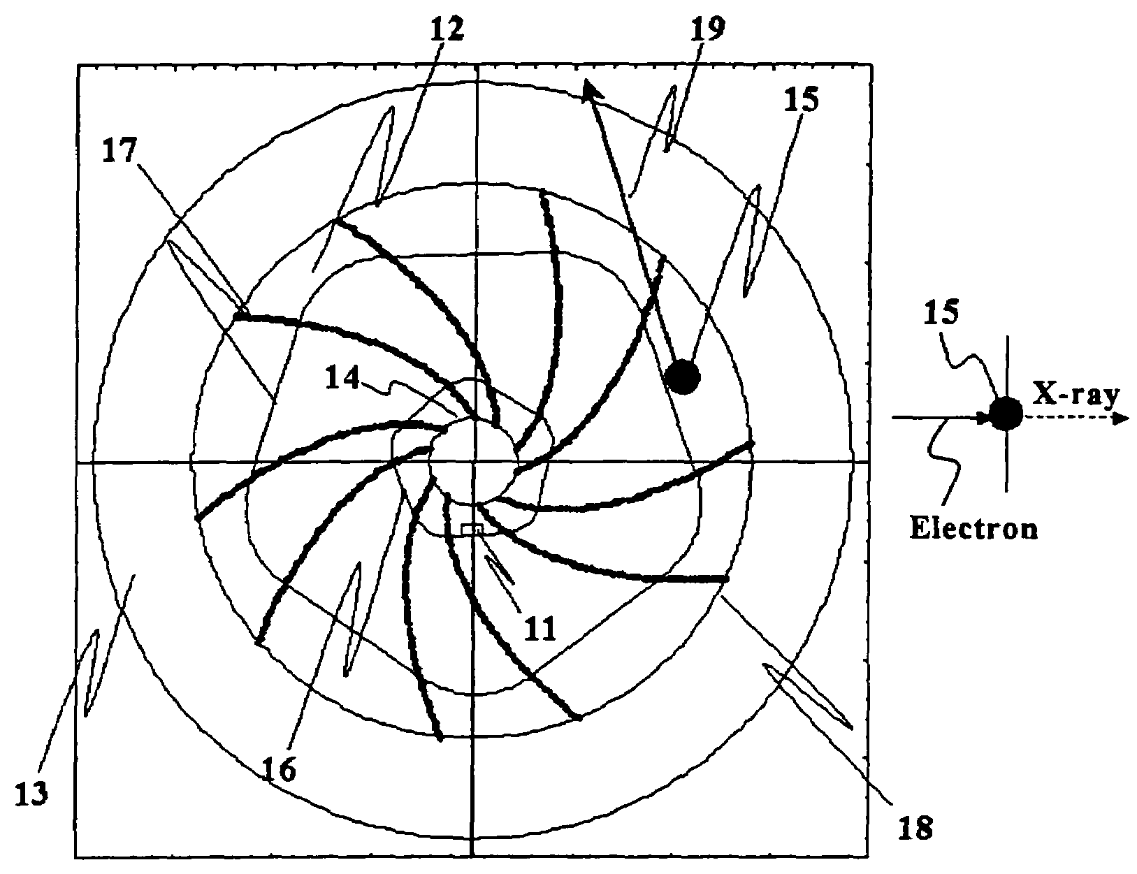
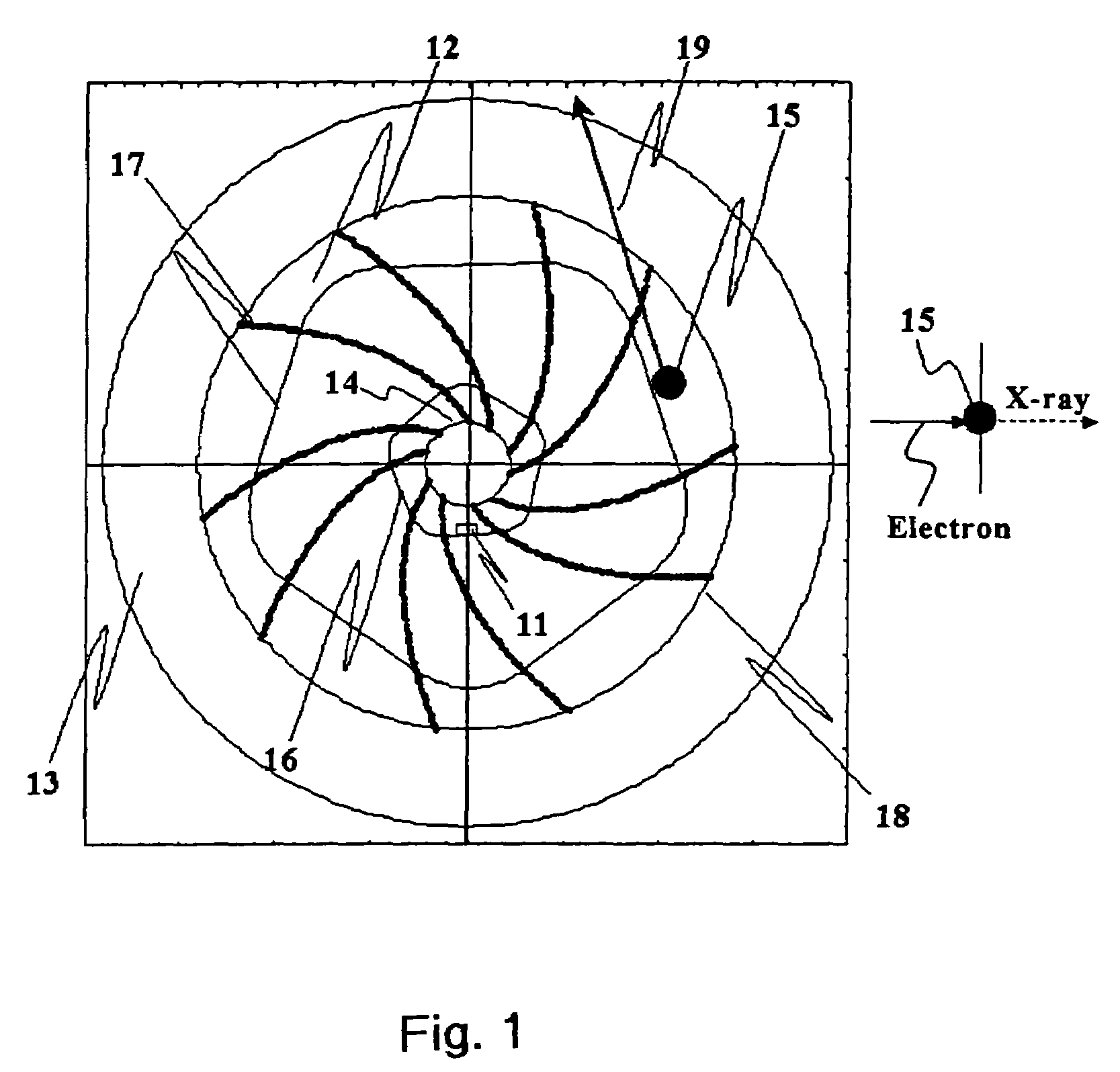
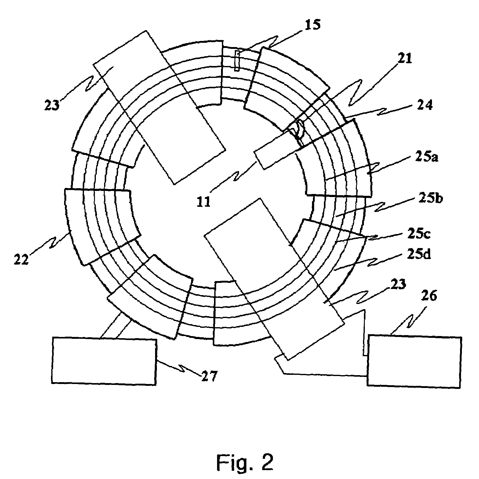
[0021]FIGS. 1 and 2 are views illustrating Configuration Example 1 and Configuration Example 2, respectively, of an electromagnetic wave generator according to Embodiment 1. Both examples have a commonality in utilizing an AG (Alternating Gradient) focusing accelerator (FIGS. 1 and 2 are taken from Non-Patent Literature 2 and Patent Literature 2, respectively); by implementing a predetermined control that utilizes the characteristics of the AG focusing accelerator, a high-performance electromagnetic wave generator can be realized.

[0022][Non-Patent Literature 2] H. Tanaka, T. Nakanishi, “DESIGN AND CONSTRUCTION OF A SPIRAL MAGNET FOR A HYBRID ACCELERATOR”, Proceedings of the 1st Annual Meeting of Particle Accelerator Society of Japan and the 29th Linear Accelerator Meeting in Japan (Aug. 4-6, 2004, Funabashi Japan), 465p-467p

[Patent Literature 2] Japanese Laid-Open Patent Publication No. 2004-296164

[0023]In FIG. 1, Reference Numeral 11 designates an electron generation device that ge...

embodiment 2

[0051]In Embodiment 2, compared with Embodiment 1, the extent to which, during the injection, an electron-beam closed orbit spreads in the radial direction is enlarged. FIG. 5 represents respective patterns 5 of changes with time of the deflection magnetic field and the acceleration-core magnetic field in the case where Embodiment 2 is applied. In FIG. 5, like reference characters designate like items in FIG. 3. The first half portion of the graph at the upper side in FIG. 5 represents an example of the case where the strength of the deflection magnetic field is constant in the entire process. In this case, the spread, in the radial direction, of an electron-beam closed orbit, due to the acceleration, is larger than that in the case of FIG. 3. The second half portion of the graph at the upper side in FIG. 5 represents an example of the case where, during the electron-beam injection, the strength of the deflection magnetic field is reduced. In this case, the spread, in the radial dir...

embodiment 3

[0052]In Embodiment 3, by changing at high speed the energy of an electron beam, the energy levels of generated X-rays are switched at high speed, without implementing injection of another electron beam. FIG. 6 represents respective patterns of changes with time of the deflection magnetic field and the acceleration-core magnetic field in the case where Embodiment 3 is applied. In FIG. 6, explanations for time points 31 to 39a are the same as those in FIG. 3. In FIG. 6, Reference Character 36a designates a time point at which an electron-beam reacceleration duration 43a corresponding to the electron-beam acceleration duration 38a starts, as well as a time point at which the control for maintaining the deflection magnetic field constant ends. Reference Character 41a designates a time point at which a target-recollision duration 44a corresponding to the target-collision duration 39a starts, as well as a time point at which the electron-beam reacceleration duration 43a ends. Reference C...


PUM


Abstract

A compact and low-cost electromagnetic wave generator in which X-rays having high intensity can be generated and the energy of generated X-rays can rapidly be switched. In an electromagnetic wave generator including a circular accelerator, a deflection electromagnet incorporated in the circular accelerator focuses injected and accelerated electrons. The circular accelerator produces stable closed electron orbits in respective regions with respective widths in the radial direction of the accelerator. The closed electron orbits are stable during injection and acceleration of electrons. A target is arranged across only some of the stable closed electron orbits so that a collision region, where a circulating electron beam collides with the target, and a non-collision region, where a circulating electron beam does not collide with the target, are produced. Through control of respective patterns of changes with time of the deflection magnetic field, a given electron closed orbit is shifted between the collision and the non-collision regions, thereby generating X-rays.

Description

BACKGROUND OF THE INVENTION[0001]1. Field of the Invention[0002]The present invention relates to an electromagnetic wave generator for generating electromagnetic waves such as X-rays, by means of electrons that, within an accelerator, circulate while forming a circular orbit.[0003]2. Description of the Related Art[0004]Conventional electromagnetic wave generators utilizing a circular accelerator include a generator (Non-Patent Literature 1) utilizing an accelerator (shortly referred to as a betatron accelerator) based on the betatron acceleration principle and a generator (Patent Literature 1) utilizing an electron storage ring.[0005]In an electromagnetic wave generator utilizing a betatron accelerator, electrons injected into the generator are accelerated, while circulating in an orbit of a constant radius; when their energy have reached a predetermined level, the electrons are made to change its orbit, whereby the electrons collide with a target arranged in the resultant orbit, th...

Claims


Application Information

Patent Timeline
Patent Type & Authority Patents(United States)
IPC IPC(8): H01J35/30
CPCH05H11/00H05H6/00H05G2/00H01J2235/08
Inventor TANAKA, HIROFUMI
Owner MITSUBISHI ELECTRIC CORP
Why Eureka
Try Eureka