
Method for optimizing a textile production process and devices applying this method

a textile production and optimization technology, applied in the field of optimizing a textile production process, can solve the problem of only very limited use possibilities of textiles

Inactive Publication Date: 2007-12-18
PICANOL NV
View PDF19 Cites 12 Cited by
  • Summary
  • Abstract
  • Description
  • Claims
  • Application Information

AI Technical Summary

Benefits of technology

[0010]According to a first possibility, the visualization comprises at least the representation of the fabric formed on the weaving machine or of a part thereof and / or of one or more fabric-determining elements. In this manner, the visualized part can be represented, for example, on a larger scale, as a result of which it becomes easier for the operator to control certain parts.
[0176]A fourteenth aspect of the invention can be used when the tension of the warp threads is measured as a function of the position of the main shaft of the loom and / or as a function of the corresponding position of a shed-forming means. According to this aspect, a characteristic of the warp thread tension in the upper warp and / or a characteristic of the warp tension in the lower warp can be shown on the screen as a function of the position of the main shaft and / or as a function of the corresponding position of the shed-forming means. This aspect of the invention, which either can be used in combination with one or more of the other aspects or not, offers the advantage that the warp tension can be shown on the screen in an easily understandable and interpretable form to any operator.

Problems solved by technology

Contrary to the embodiments already known, whereby at the machine information exclusively in the form of signs, a written text or codes is represented, which has as a disadvantage that the usage possibilities thereof are only very restricted, now, by visualizing, according to the invention, characteristics of the fabric and / or factors determining the fabric by means of an image or a series of images on the machine screen, the operator or such will view a realistic picture, as a result of which a direct visual control is made possible.

Method used


Image

  • Method for optimizing a textile production process and devices applying this method
  • Method for optimizing a textile production process and devices applying this method
  • Method for optimizing a textile production process and devices applying this method

Examples


Embodiment Construction

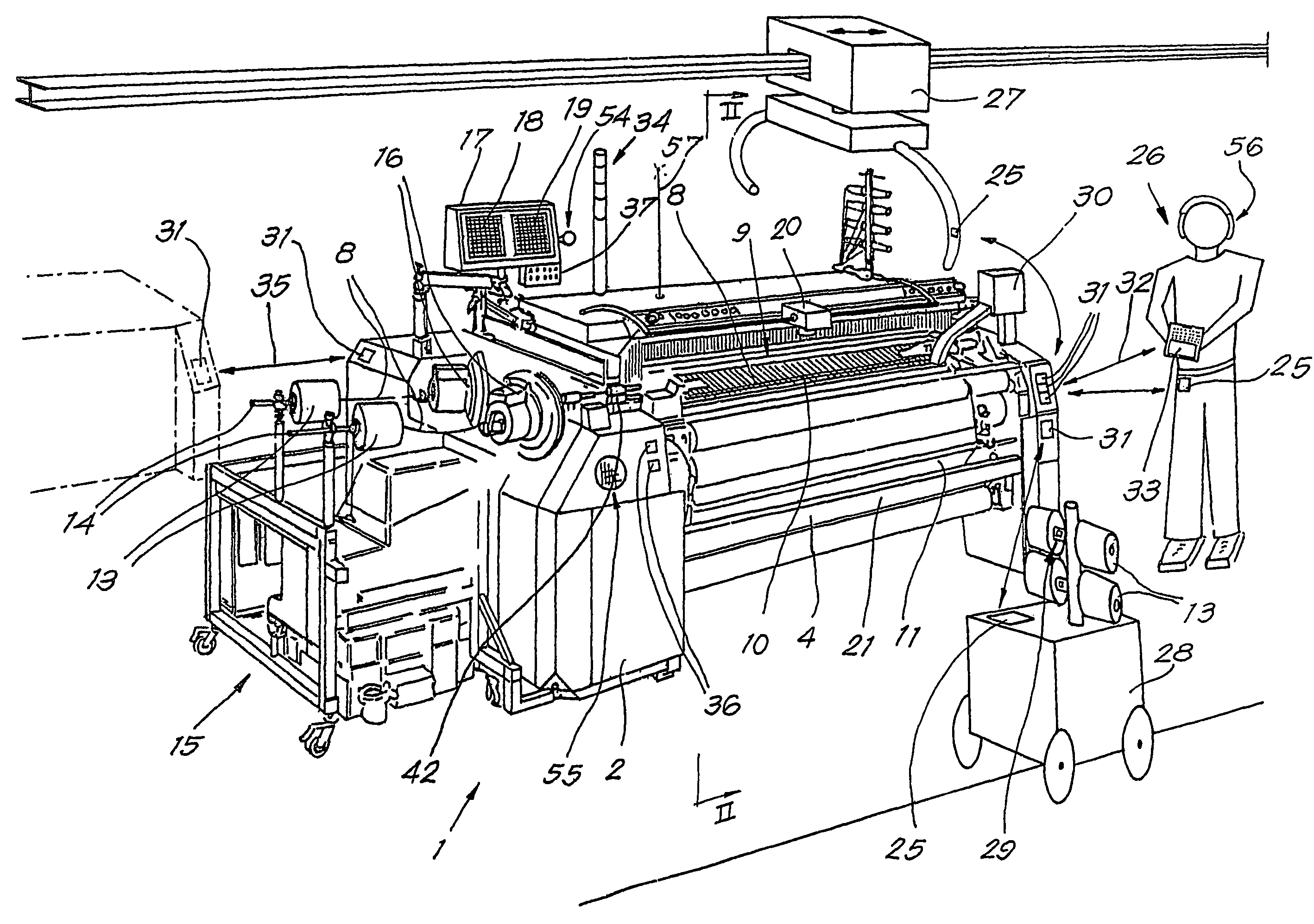
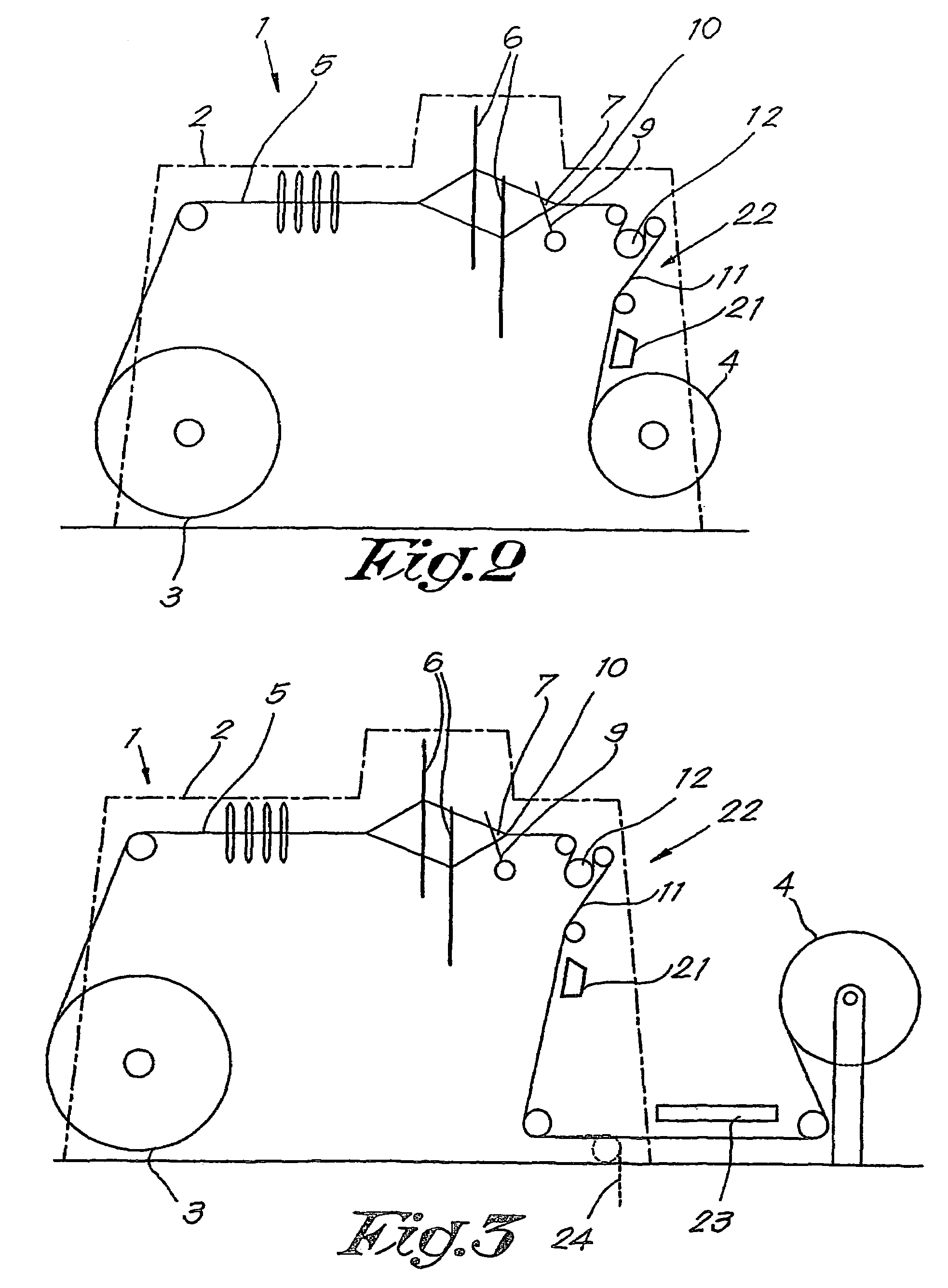
[0186]In FIGS. 1 and 2, a weaving machine 1 is represented which, as known, includes a chassis 2 in which a warp beam 3 and a cloth roll 4 can be provided. In a known manner, thereby warp threads 5 are wound off the warp beam 3 and fed through weaving frames 6, such that a shed 7 is formed, in which weft threads 8 can be beaten, by means of the reed 9, against the beating line 10 of the already formed cloth or fabric 11. The formed cloth 11 is transported off by means of a number of rolls, amongst which the so-called sand roll 12, in order to be wound onto the cloth roll 4.

[0187]The weft threads 8 are supplied in a known manner from bobbins 13, which are mounted on pins 14 of a bobbin rack 15, by the intermediary of prewinders 16.

[0188]The weaving machine 1 is provided with a machine terminal 17.

[0189]According to said first aspect of the invention, as explained in the a foregoing, different visualizations are realized on the machine terminal 17, which comprises, amongst others, a c...


PUM


Abstract

Method for optimizing a textile production process, which consists in manufacturing a fabric (11) on a weaving machine (1), characterized in that characteristics of the fabric (11) and / or fabric-determining elements are visualized on a machine screen by means of at least one image.

Description

BACKGROUND[0001]A. Field of the Invention[0002]This invention relates to a method for optimizing a textile production process, as well as to devices applying this method.[0003]B. Related Art[0004]By the term textile production process, it is intended to mean all processes which are related to the production of textile products, where, in respect to products, weaving products specifically are meant and, more generally, other textile products may be included, such as products which are manufactured in a spinning mill. With respect to devices for textile production, weaving machines are intended, although more generally, other devices may be included, including peripherical devices for such devices.[0005]It is known that with textile production processes, in particular with weaving processes, it is important that the continuity of a smooth operation is assured and, with a possible intervention of an operator or such, that the operation runs as smooth as possible. A problem with the kno...

Claims


Application Information

Patent Timeline
Patent Type & Authority Patents(United States)
IPC IPC(8): G06F19/00D03D51/18D03J1/00D03J1/24D06H3/08
CPCD03D51/18D03J1/005D06H3/08D03J1/24D03J1/007
Inventor VERGOTE, FILIPROUZERE, ANTONYPEETERS, JOZEF
Owner PICANOL NV
Learn More