Powered driver with location specific switching

a technology of location-specific switching and power drivers, applied in the direction of screwdrivers, power driven tools, wrenches, etc., can solve the problems of inapplicability of electrical drivers, inability to use the same driver for different fasteners, and inability to accurately and repeat the approach, etc., to achieve high accuracy and repeatability, cost-effective

Inactive Publication Date: 2007-12-25
AMERICAN POWER TOOLS
View PDF12 Cites 36 Cited by
  • Summary
  • Abstract
  • Description
  • Claims
  • Application Information

AI Technical Summary

Benefits of technology

[0004]This invention provides improved drivers and methods for manipulating threaded connectors that accommodate repeated precise tightening of threaded connectors based on location specific switching. The driver of this invention is capable of application over a wide variety of fastener types, independent of torque requirements and / or fastener size. The drivers and methods of this invention are appropriate for both pneumatic and electrical applications. Specified fastener tightening using the drivers and methods of this invention is highly accurate and repeatable, while yet maintaining a cost effective tool for both manufacturing and field applications.
[0009]It is therefore an object of this invention to provide improved drivers and methods for manipulating threaded connectors.
[0012]It is yet another object of this invention to provide powered nut drivers and methods that provide automatic cessation of driver rotation upon achievement of selected relative locations of two movable parts of the driver corresponding to correct nut tightness.
[0013]It is another object of this invention to provide a powered tool driver capable of application with a wide variety of connector and fastener types, torque requirements and / or size, that is adaptable for both pneumatic and electrical applications, and that can achieve specified connector tightening in a highly accurate and repeatable manner.
[0016]It is another object of this invention to provide a method for reliably repeatable rotation of threaded line fitting nuts to a selected tightness that includes the steps of engaging the nut at a rotatable socket and rotating the nut in one direction, engaging another part of the line fitting at a reaction unit movably maintained adjacent to the socket and biasing the reaction unit toward the socket during rotation of the engaged nut in the one direction, gauging relative locations of the reaction unit and the socket during rotation in the one direction, and, responsive to the gauging, causing cessation of rotation when a selected relative location of the reaction unit and the socket is achieved corresponding to selected nut tightness.

Problems solved by technology

Torque requirements for driving large and small fasteners varies such that the same driver often can not be employed for different fasteners.
Moreover, devices and methods for gauging fitting integrity during fitting installation that are used for pneumatic tools are frequently not applicable for electrical drivers and vice versa.
Such heretofore known approaches are often not highly accurate and repeatable, and / or are quite expensive computer-based applications of limited utility in the field.

Method used


Image

  • Powered driver with location specific switching
  • Powered driver with location specific switching
  • Powered driver with location specific switching

Examples


Embodiment Construction

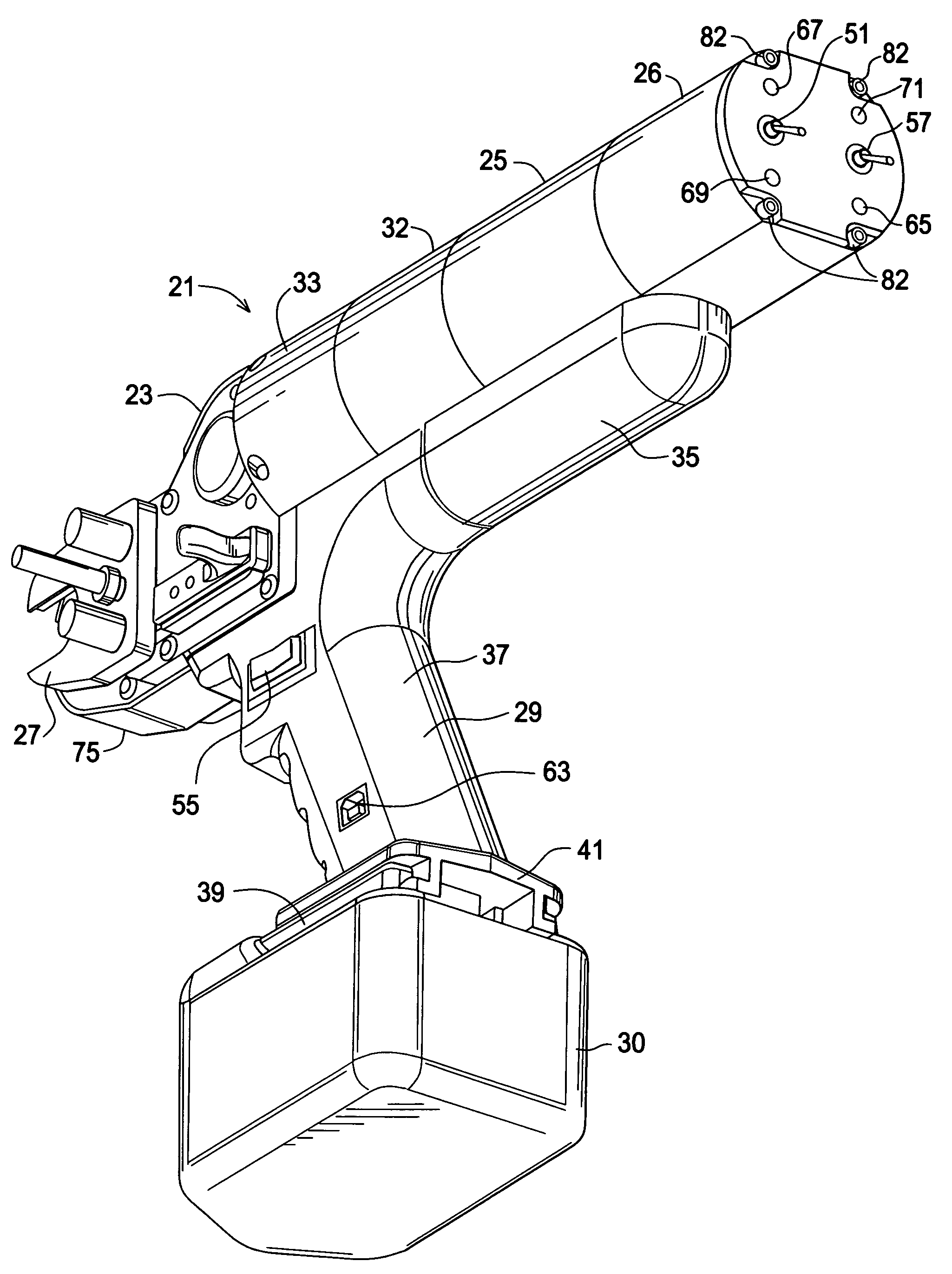
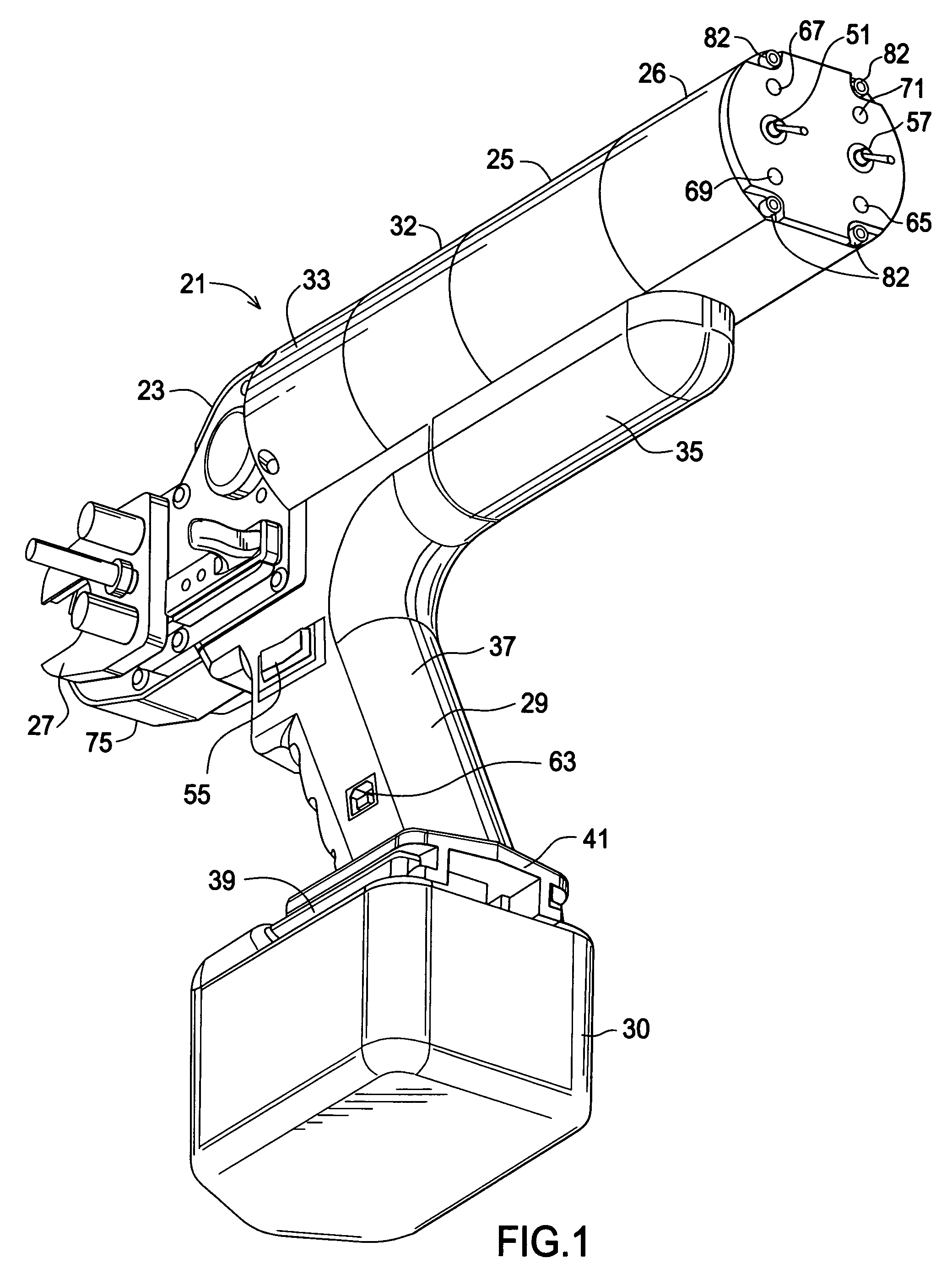
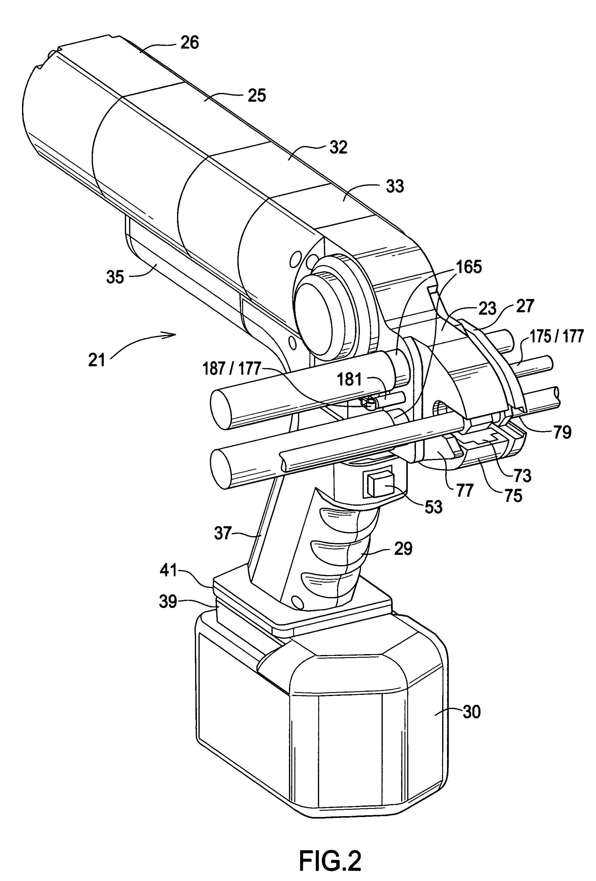
[0032]Powered driver 21 of this invention, for rotating tools such as sockets or the like to manipulate threaded connectors, is illustrated in FIGS. 1 through 3. Driver 21 includes driver head 23, motor module 25 (any means of applying motive force could be used including electrical, pneumatic or fluid drive motors), electronics module 26, reaction unit 27, housing 29, and battery pack 30. Torque amplification drive train modules 32 and 33 provide a drive train capable of staged increase of torque from a motor 25 rating of about 0.18 ft.lbs. to over 35 ft.lbs., thereby accommodating connector manipulation in a wide variety of size and torque application categories (torque amplification is adaptable to requirements). Housing 29 is hollow at both barrel portion 35 and handle portion 37 thus providing the required space and protection for driver electrical components as hereinafter discussed. Battery pack 30 is of standard configuration and includes a standard conductive slide connecto...


PUM


Abstract

Powered drivers and methods are disclosed, the drivers including a head housing a motor driven drive transfer assembly for operating a rotatable socket engageable at a threaded connector. A reaction unit having a fitting engagement attached to rail guides is movably maintained through the head. A biasing unit is maintained at the head and is operatively associated with the rail guides of the reaction unit to bias the fitting engagement of the reaction unit toward the rotatable socket during tightening rotation of the engaged threaded connector. A probe and switch are associated with different ones of the reaction unit and the head, and are brought into operative association at selected relative locations of the reaction unit and the head during connector rotation to cause motor cessation.

Description

FIELD OF THE INVENTION[0001]This invention relates to drivers for tools, and, more particularly, relates to powered nut drivers.BACKGROUND OF THE INVENTION[0002]Powered drivers, both pneumatic and electrical, for manipulation of various types of tools such as sockets for threaded connectors are well known. In many applications, such as manipulation of threaded line fittings (i.e., unions or the like) found in all gas or liquid processing or delivery operations and assemblies, the tightness of the fitting is critical to assure a sound connection and to avoid leakage (which may occur if line fittings are either over or under tightened).[0003]Numerous approaches to gauging the correct tightness of such connectors have been heretofore suggested and / or utilized, with varying degrees of success. Torque requirements for driving large and small fasteners varies such that the same driver often can not be employed for different fasteners. Moreover, devices and methods for gauging fitting inte...

Claims


Application Information

Patent Timeline
Patent Type & Authority Patents(United States)
IPC IPC(8): B25B23/145B25B23/147B25B21/00
CPCB25B13/481B25B21/00B25B23/147B25B23/145B25B21/002
Inventor WILSON, JR., DAVID
Owner AMERICAN POWER TOOLS
Why Eureka
Try Eureka