Swingable vehicle

a technology of swinging vehicle and swinging shaft, which is applied in the direction of monocoque construction, transportation and packaging, cycles, etc., can solve the problems of limiting the freedom of design, limiting the swing angle, and limiting the vehicle suspension, so as to reduce the overall length of the drive shaft, reduce the width, and increase the bend angle

Inactive Publication Date: 2007-12-25
HONDA MOTOR CO LTD
View PDF22 Cites 56 Cited by
  • Summary
  • Abstract
  • Description
  • Claims
  • Application Information

AI Technical Summary

Benefits of technology

[0027]It is an object of the present invention to enlarge the bend angles of constant velocity joints, to make it possible to reduce the overall length of drive shafts and thereby reduce the vehicle width. Thus, an increase in the freedom in designing the suspension and the swing angle for a swingable vehicle is obtained.

Problems solved by technology

Therefore, even in the case of a small vehicle where it is desirable to reduce the vehicle width, a reduction in the vehicle width is limited due to the need to secure the vertical stroke.
In addition, the limitation as to the bend angle of the slide type triport joint 404 causes limitations as to the freedom in design, such as specifications, size and layout, of the suspension in the vehicle.
In addition, in the case of using the slide type triport joint 404 for a swingable vehicle, for example, the bend angle may limit the swing angle.

Method used


Image

  • Swingable vehicle
  • Swingable vehicle
  • Swingable vehicle

Examples


Embodiment Construction

[0081]The best mode for carrying out the present invention will be described below, based on the accompanying drawings.

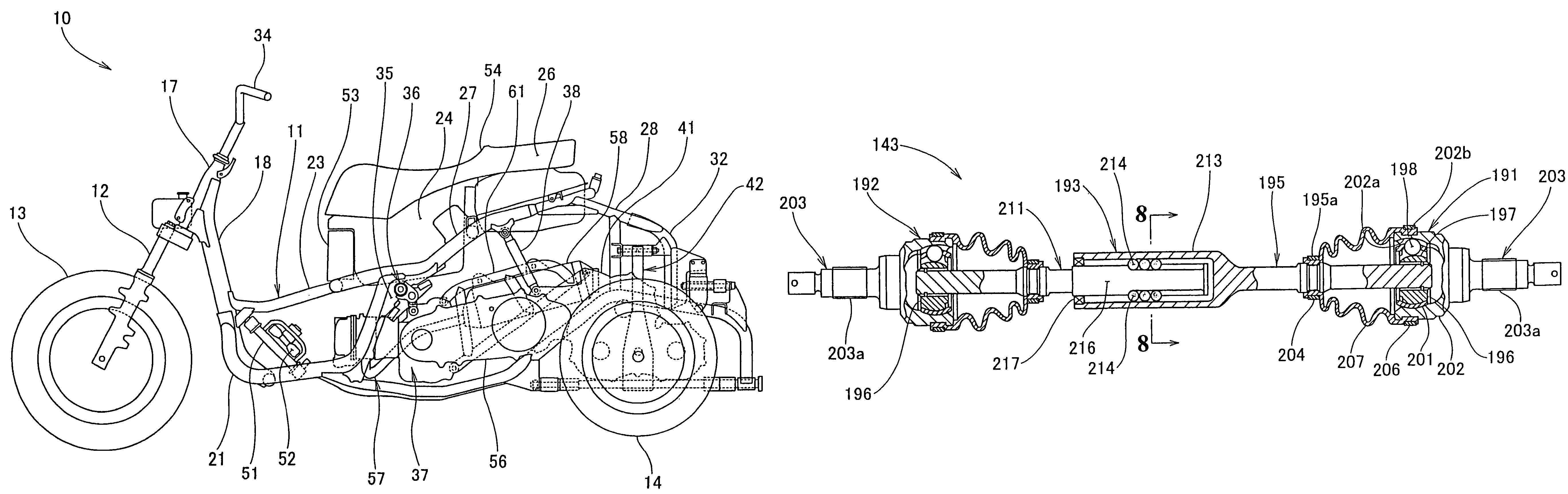
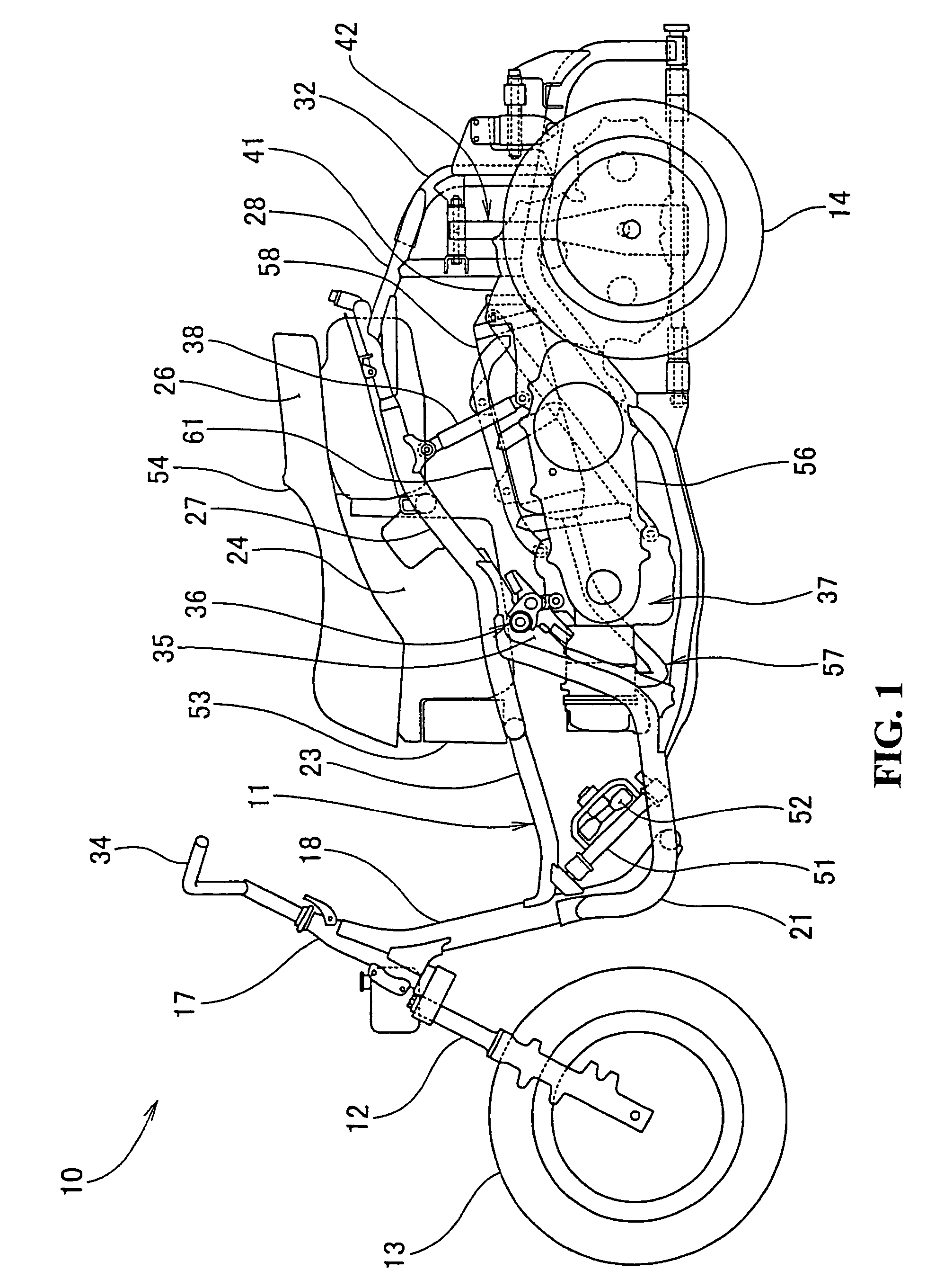
[0082]FIG. 1 is a side view of a swingable vehicle according to the present invention. The swingable vehicle 10 is a swingable three-wheel vehicle in which a front wheel 13 is mounted to a front portion of a vehicle body frame 11 through a front fork 12. Rear wheels 14 and 15 (only symbol 14 on the viewer's side is shown) as left and right wheels are mounted to rear portions of the vehicle body frame 11 through left and right suspension arms (described in detail later). The vehicle frame 11 is swingable in the left-right direction relative to the suspension arms at the time of turning, for example.

[0083]The vehicle body frame 11 includes a head pipe 17 provided at the front end, a down pipe 18 extending substantially downwardly from the head pipe 17, lower pipes 21 and 22 (only symbol 21 on the viewer's side is shown) extending in roughly a U-shape in side view to t...


PUM


Abstract

A left drive shaft and a right drive shaft each include an inside constant velocity joint and an outside constant velocity joint with a ball spline mechanism provided between the inside constant velocity joint and the outside constant velocity joint for enabling the distance between the inside constant velocity joint and the outside constant velocity joint to be contracted and extended. The ball spline mechanism includes a spline shaft having an outer circumferential surface provided with a plurality of axial grooves extending in the axial direction, a tubular portion surrounding the periphery of the spline shaft and having an inner circumferential surface provided with a plurality of axial grooves extending in the axial direction and a plurality of balls capable of rolling while being fitted in the axial grooves and in the axial grooves. In addition, a left lower arm and a right lower arm are formed into an A-shape and are supported by a lower part of a rising portion and a lower end of the downwardly extending portion via a lower supporting shaft.

Description

CROSS-REFERENCE TO RELATED APPLICATIONS[0001]The present application is related to Japanese Patent Application Nos. 2003-341725; 2003-342156 and 2003-376282 all filed on Sep. 30, 2003 the entire contents of which are hereby incorporated by reference.BACKGROUND OF THE INVENTION[0002]1. Field of the Invention[0003]The present invention relates to a swingable vehicle.[0004]2. Description of Background Art[0005]Hitherto, a swingable vehicle is known wherein a slide type triport joint is used at one end of a drive shaft for being connected between a final speed reduction gear and a wheel. See, Japanese Utility Model Laid-open No. Sho 63-43905.[0006]FIG. 1 of Japanese Utility Model Laid-open No. Sho 63-43905 will be described referring to FIG. 15 of the present specification. However, the reference numeral have been changed.[0007]FIG. 15 is a side view of a drive shaft for a swingable vehicle according to the prior art, wherein a slide type triport joint 404 is used on the wheel 402 side ...

Claims


Application Information

Patent Timeline
Patent Type & Authority Patents(United States)
IPC IPC(8): B62D61/06B62D21/00B62D23/00B62K5/02B60G21/00B62D9/02B62K5/027
CPCB60G21/007B62K5/10B62D9/02B62K5/027B60G2200/14B60G2200/144B60G2200/422B60G2200/46B60G2204/13B60G2204/421B60G2300/122B60G2202/312
Inventor TAKAYANAGI, SHINJIMAKATA, YOHEIKOBAYASHI, HIROYOSHI
Owner HONDA MOTOR CO LTD
Why Eureka
Try Eureka