Pellet loader

a technology of loader and loader body, which is applied in the direction of conveyors, conveyors, transportation and packaging, etc., can solve the problems of reducing transportation efficiency, dimensional accuracy and material quality change during machining, and affecting the change of material quality and dimensional accuracy. the effect of pressure inside the container is not reduced and not crushed

Inactive Publication Date: 2007-12-25
ITSWA
View PDF20 Cites 83 Cited by
  • Summary
  • Abstract
  • Description
  • Claims
  • Application Information

AI Technical Summary

Benefits of technology

[0022]In addition, even if the container is an airtight flexible bag or an airtight container, the pressure inside the container is not reduced and the container is not crushed.

Problems solved by technology

However, a small-sized pellet loader is equipped with a small and long insert pipe to suck pellets, therefore, it has a problem in that pellets are entwined inside the insert pipe and clog it.
Particularly, in case that pellets are made of resin including fiberglass, they are entwined with each other due to a fiber end protruding from the surface thereof, which reduced the transportation efficiency remarkably.
In addition, an insert pipe sucks moistened outside air together with pellets, so that the pellets are humidified during sucking, which causes a problem in that the dimensional accuracy and change in material quality during machining are affected.

Method used


Image

  • Pellet loader
  • Pellet loader
  • Pellet loader

Examples


Embodiment Construction

[0032]The pellet loader according to the present invention will be described in detail hereinafter with reference to the attached drawings.

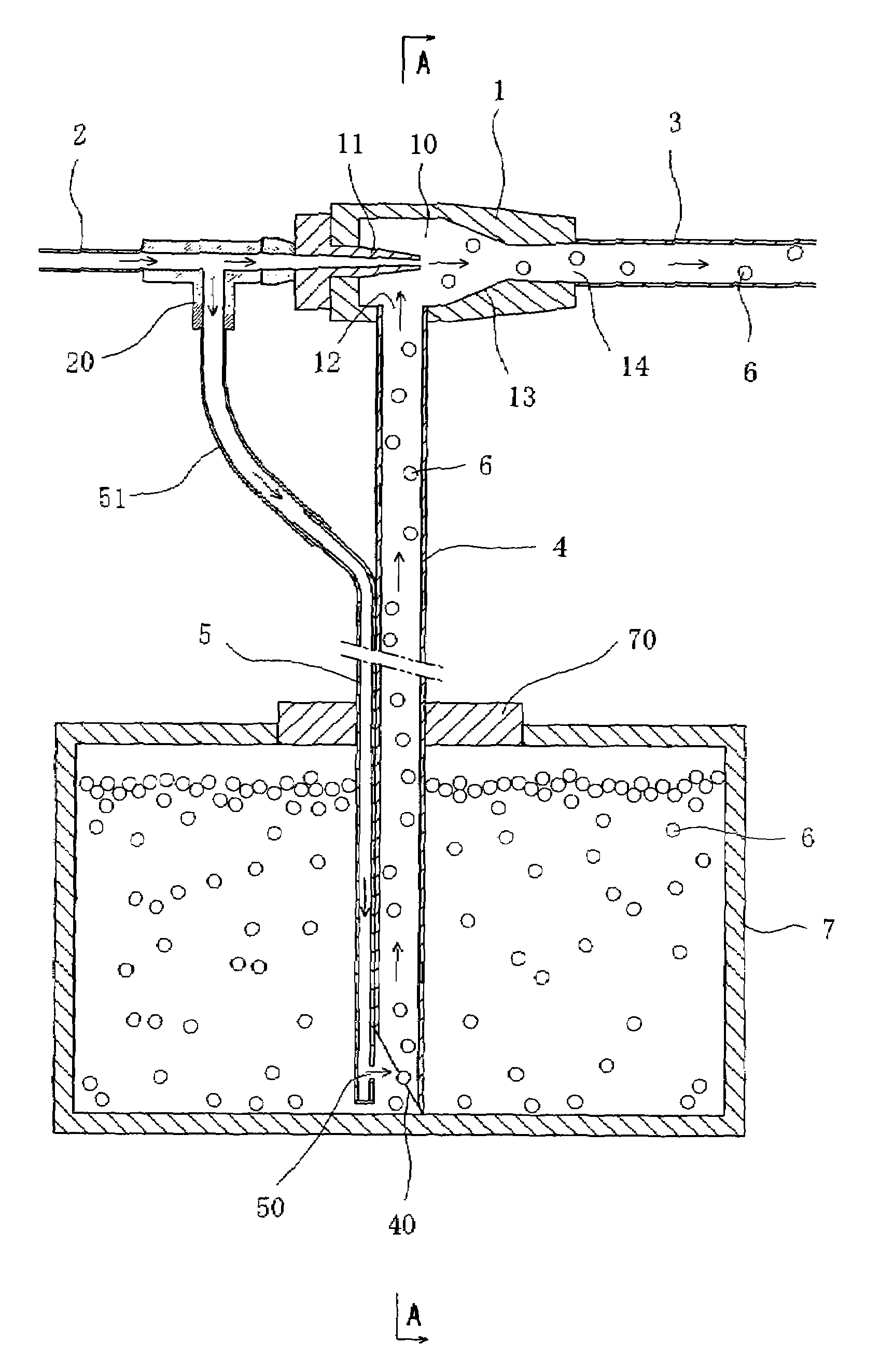
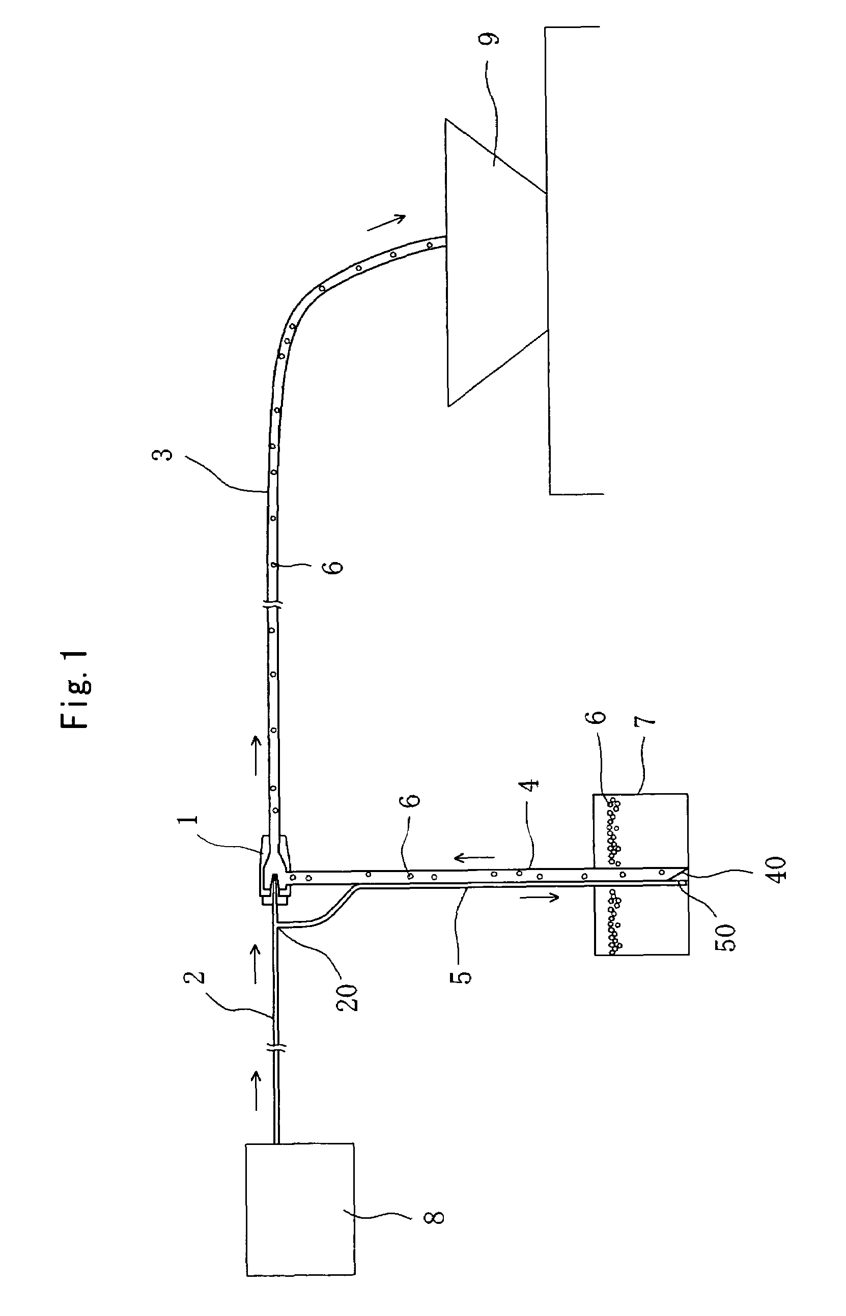
[0033]FIG. 1 is a view of a pellet loader according to an embodiment of the present invention, in which the pellet loader is in use. FIG. 2 is a cross-sectional view for illustrating a structure and operation of the pellet loader shown in FIG. 1. FIG. 3 is a partial cross-sectional view along A-A line in FIG. 2.

[0034]Referring to FIGS. 1 and 2, the reference numeral 1 designates an ejector portion and the reference numeral 10 designates a low pressure chamber arranged in the ejector portion 1. The ejector portion 1 is provided with an injection nozzle 11 in the low pressure chamber 10. A gas supply pipe 2 is connected to the injection nozzle 11. One end (upper end) of an insert pipe 4 is connected to a suction port 12 of the ejector portion 1. The insert pipe 4 is adapted to suction pellets 6 into the low pressure chamber 10 of the ejector portio...


PUM


Abstract

A pellet loader according to the present invention is provided with an ejector portion 1. A gas supply pipe 2 is connected to an injection nozzle 11 of the ejector portion 1 for supplying compressed gas from a compressed gas source 8. An insert pipe 4 is connected to a suction inlet 12 of the ejector portion 1. Pellets are sucked from the suction inlet 40 of the insert pipe 4 into the ejector portion 1. A gas pipe 5 is arranged along the insert pipe 4 and one end of the gas pipe 5 has an opening 50 positioned at the vicinity of the suction inlet 40 of the insert pipe 4 and faced to the suction inlet 40 of the insert pipe 4 for injecting the compressed gas into the insert pipe 4. A transport pipe 3 is connected to an outlet portion 14 of the ejector portion 1.

Description

TECHNICAL FIELD[0001]The present invention relates to a pellet loader for transporting pellets stored in a container to a predetermined place through a transport pipe by compressed gas.BACKGROUND ART[0002]When transporting pellets stored in a container to a predetermined place, a pellet loader is used. As one of pellet loaders, an ejector type employing with compressed gas is known in the prior art.[0003]As shown in FIG. 7, the ejector-type pellet loader comprises an ejector portion 1 having an injection nozzle 11 to which a gas supply pipe 2 is connected. A suction inlet 12 of the ejector portion 1 is provided with an insert pipe 4 and a transport pipe 3 is connected to an outlet portion 14 of the ejector portion 1.[0004]When this pellet loader is used, the insert pipe 4 is inserted among pellets 6 stored in a container 7. Compressed gas is fed into the ejector portion 1 from a compressed gas source through the gas supply pipe 2, whereby the pellets 6 are sucked into the ejector po...

Claims


Application Information

Patent Timeline
Patent Type & Authority Patents(United States)
IPC IPC(8): B65G53/10
CPCB65G53/26B65G53/14
Inventor OGASAHARA, MINORUUEKI, TATSUYA
Owner ITSWA
Why Eureka
Try Eureka